The following paragraphs describe the registers that make up a status group and explain the status information that each status group provides.
Status Group Registers
In general, a status group consists of a condition register, a transition filter, an event register, and an enable register. Each component is briefly described in the following paragraphs.
Condition Register
The condition register is continuously updated to reflect the current status of the MG362x1A. There is no latching or buffering for this register, it is updated in real time. Reading the contents of a condition register does not change its contents.
Transition Filter
The transition filter is a special register that specifies which types of bit state changes in the condition register will set corresponding bits in the event register. Negative transition filters (NTR) are used to detect condition changes from True (1) to False (0); positive transition filters (PTR) are used to detect condition changes from False (0) to True (1). Setting both positive and negative filters True allows an event to be reported anytime the condition changes. Transition filters are read-write. Transition filters are unaffected by queries or *CLS (clear status) and *RST commands.
The command :STATus:PRESet sets all negative transition filters to all 0’s and sets all positive transition filters to all 1’s.
Event Register
The event register latches transition events from the condition register as specified by the transition filter. Bits in the event register are latched, and once set they remain set until cleared by a query or a *CLS command. Event registers are read only.
Enable Register
The enable register specifies the bits in the event register that can produce a summary bit. The MG362x1A logically ANDs corresponding bits in the event and enable registers, and ORs all the resulting bits to obtain a summary bit. Summary bits are recorded in the Summary Status Byte. Enable registers are read-write. Querying an enable register does not affect it.
The command :STATus:PRESet sets the Operational Status Enable register and the Questionable Status Enable register to all 0’s.
MG362x1A Status-Reporting Structure
Status Group Reporting
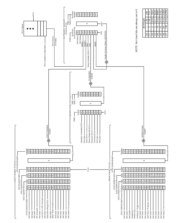
The state of certain MG362x1A hardware and operational events and conditions can be determined by programming the status system. As shown in Figure: MG362x1A Status-Reporting Structure, the three lower status groups provide status information to the Summary Status Byte group. The Summary Status Byte group is used to determine the general nature of an event or condition and the other status groups are used to determine the specific nature of the event or condition.
Note
Programming commands for the status system, including examples of command usage, can be found in Programming Commands.
The following paragraphs explain the information that is provided by each status group.
Summary Status Byte Group
The Summary Status Byte group, consisting of the Summary Status Byte Enable register and the Summary Status Byte, is used to determine the general nature of a MG362x1A event or condition. The bits in the Summary Status Byte provide the following information:
Summary Status Byte
Bit
Description
0, 1
Not Used. These bits are always set to 0.
2
Set to indicate the Error Queue contains data. The Error Query command can then be used to read the error message(s) from the queue.
3
Set to indicate the Questionable Status summary bit has been set. The Questionable Status Event register can then be read to determine the specific condition that caused the bit to be set.
4
Set to indicate that the MG362x1A has data ready in its output queue.
5
Set to indicate that the Standard Event Status summary bit has been set. The Standard Event Status register can then be read to determine the specific event that caused the bit to be set.
6
Set to indicate that the MG362x1A has at least one reason to require service. The individual bits in the Status Byte are ANDed with their corresponding Service Request Enable Register bits, then each bit value is ORed and input to this bit.
7
Set to indicate that the Operational Status summary bit has been set. The Operational Status Event register can then be read to determine the specific condition that caused the bit to be set.
Standard Event Status Group
The Standard Event Status group, consisting of the Standard Event Status register (an Event register) and the Standard Event Status Enable register, is used to determine the specific event that set bit 5 of the Summary Status Byte. The bits in the Standard Event Status register provide the following information:
Standard Event Status
Bit
Description
0
Set to indicate that all pending MG362x1A operations were completed following execution of the “*OPC” command.
1
Not Used. The bit is always set to 0.
2
Set to indicate that a query error has occurred. Query errors have SCPI error codes from –499 to –400.
3
Set to indicate that a device-dependent error has occurred. Device-dependent errors have SCPI error codes from –399 to –300 and 1 to 32767.
4
Set to indicate that an execution error has occurred. Execution errors have SCPI error codes from –299 to –200.
5
Set to indicate that a command error has occurred. Command errors have SCPI error codes from –199 to –100.
6,7
Not Used. The bits are always set to 0.
Operational Status Group
The Operational Status group, consisting of the Operational Condition register, the Operational Positive Transition register, the Operational Negative Transition register, the Operational Event register, and the Operational Event Enable register, is used to determine the specific condition that set bit 7 in the Summary Status Byte. The bits in the Operational Event register provide the following information:
Operational Status Event
Bit
Description
0–2
Not Used. The bits are always set to 0.
3
Set to indicate that a sweep is in progress.
4
Set to indicate that the MG362x1A is measuring.
5
Set to indicate that the MG362x1A is in an armed “wait for trigger” state.
6
Not Used. The bit is always set to 0.
7
Not Used. The bit is always set to 0.
8
Not Used. The bit is always set to 0.
9
Set to indicate that MG362x1A self-test is in progress.
10–14
Not Used. The bits are always set to 0.
*15
Always 0. The use of Bit 15 is not allowed by SCPI.
Questionable Status Group
The Questionable Status group, consisting of the Questionable Condition register, the Questionable Positive Transition register, the Questionable Negative Transition register, the Questionable Event register, and the Questionable Event Enable register, is used to determine the specific condition that set bit 3 in the Summary Status Byte. The bits in the Questionable Event register provide the following information:
Questionable Event Status
Bit
Description
0–2
Not Used. The bits are always set to 0.
3
Set to indicate an RF unleveled condition.
4
Not Used. The bit is always set to 0.
5
Set to indicate a phase-lock error or RF unlocked condition.
6
Not Used. The bit is always set to 0.
7
Set to indicate a modulation range error.
8
Not Used. The bit is always set to 0.
9
Set to indicate that self-test failed.
10
Not Used. The bit is always set to 0.
11
Not Used. The bit is always set to 0.
12-14
Not Used. The bits are always set to 0.
*15
Always 0. The use of Bit 15 is not allowed by SCPI.