The rack mounting kit (Option 1) contains a set of track slides, mounting ears, and front panel handles for mounting the Rubidium MG362x1A into a standard equipment rack. The following procedure provides instructions for installing the rack mounting hardware on the instrument. The rack mounting kit uses the same inner assembly without the slide.
Note
If installing into a rack mount console, the rack mount must be grounded and furnished with a manual power shutoff.
1. Disconnect the power cord and any other cables from the instrument.
2. Using a Phillips screwdriver, remove the screws and the front handle assemblies (7) from the instrument. (For instruments not having front handles, remove the screws and the front top and bottom feet from the instrument.) Retain the screws.
3. Remove the four feet (1) from the rear of the instrument. Retain the screws.
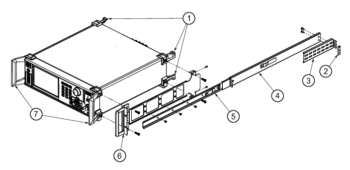
Front Handle and Feet Removal
1. Rear Feet (4)
2. Nut Bar
3. Extension Bracket
4. Outer Slide Assembly
5. Inner Slide Assembly
6. Rack Mount Bracket
7. Front Handles (2)
Note
The screws with green heads have metric threads. When it becomes necessary to replace any of these screws, always use the exact replacement green-headed screws to avoid damage to the instrument.
Install Hardware
Refer to the rack mount kit. Use this procedure to install the two rack mounts slides to both the left and right sides of the instrument.
1. Install the rack mount brackets (6) to the instrument.
2. Remove the inner slide assemblies (5) from the outer slide assemblies (4).
3. Install the side inner slide assemblies (5) onto the instrument case.
4. Install the extension brackets (3) onto the outer slide assemblies using the screws and nut bars (2)
5. Insert two green-headed screws through the holes in the slide assemblies behind the handle and into the metric tapped holes in the side of the instrument.
6. Insert two green-headed screws through the holes near the rear of the slide assemblies and into the metric tapped holes in the side of the instrument.
7. Insert the two SAE threaded screws (removed from the feet) through the tabs on the rear of the slide assemblies and into the rear panel of the instrument.
8. Using the Phillips screwdriver, tighten all screws holding the left side slide assemblies to the instrument chassis.
9. Lift the signal generator into position. Align the inner and outer slide assemblies and slide the instrument into the rack. Realign the hardware as needed for smooth operation.