The MG362x1A fully supports the IEEE-802.3 standard. Most MG362x1A front panel functions (except power on/off) can be remotely controlled via a network server and an Ethernet connection. The MG362x1A software supports the TCP/IP network protocol.
Ethernet uses a bus or star topology where all of the interfacing devices are connected to a central cable called the bus, or are connected to a hub. Ethernet uses the CSMA/CD access method to handle simultaneous transmissions over the bus. CSMA/CD stands for Carrier Sense Multiple Access/Collision Detection. This standard enables network devices to detect simultaneous data channel usage, called a collision, and provides for a contention protocol. When a network device detects a collision, the CSMA/CD standard dictates that the data will be retransmitted after waiting a random amount of time. If a second collision is detected, the data is again retransmitted after waiting twice as long. This is known as exponential back off.
The TCP/IP setup requires the following:
• IP Address: Every computer/electronic device in a TCP/IP network requires an IP address. An IP address has four numbers (each between 0 and 255) separated by periods. For example: 128.111.122.42 is a valid IP address.
• Subnet Mask: The subnet mask distinguishes the portion of the IP address that is the network ID from the portion that is the station ID. The subnet mask 255.255.0.0, when applied to the IP address given above, would identify the network ID as 128.111 and the station ID as 122.42. All stations in the same local area network should have the same network ID, but different station IDs.
• Default Gateway: A TCP/IP network can have a gateway to communicate beyond the LAN identified by the network ID. A gateway is a computer or electronic device that is connected to two different networks and can move TCP/IP data from one network to the other. A single LAN that is not connected to other LANs requires a default gateway setting of 0.0.0.0. If you have a gateway, then the default gateway would be set to the appropriate value of your gateway
• Ethernet Address: An Ethernet address is a unique 48-bit value that identifies a network interface card to the rest of the network. Every network card has a unique Ethernet address permanently stored into its memory. Remote programming and operation between the instrument and remote program is accomplished via a TCP/IP raw socket connection to port 9001. The remote program must establish a TCP/IP raw socket connection at port 9001 to the MG362x1A.
• Remote programming and operation between the instrument and remote program is accomplished via a TCP/IP raw socket connection to port 9001. The remote program must establish a TCP/IP raw socket connection at port 9001 to the MG362x1A.
• The remote program may connect to the instrument IP address or to its HOSTNAME (Ethernet only). If using DHCP instead of a static IP, using the HOSTNAME may be more reliable for finding an instrument on a network.
• You may need to contact your network administrator to ensure network security policies, anti-virus, and firewall settings do not block access to the controlling computer and its ports.
Interface between the signal generator and other devices on the network is via a category five (CAT-5) interface cable connected to a network. This cable uses four twisted pairs of copper insulators terminated into an RJ45 connector. CAT-5 cabling is capable of supporting frequencies up to 100 MHz and data transfer speeds up to 1 Gbps, which accommodates 1000Base-T, 100Base-T, and 10Base-T networks. CAT-5 cables are based on the EIA/TIA 568 Commercial Building Telecommunications Wiring Standard developed by the Electronics Industries Association.
The instrument can be remotely programmed using the raw sockets over TCP/IP protocol. The NI-VISA™ I/O library is used on the server side to facilitate the communications. The SCPI or MG362x1A command sets listed in the MG362x1A programming manual (10370-10385) applies to LAN programming as well.
To run the following example, you must have NI-VISA 2.5 or later installed on the controller PC and you must select the VISA library (visa32.dll) as a reference in a Visual Basic project. Both the MG362x1A instrument and the host PC must be connected to the network.
Network Connection
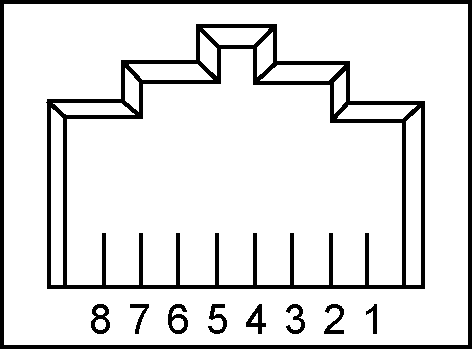
Interface between the instrument and other devices on the network is via a category five (CAT‑5) interface cable connected to a network. This cable uses four twisted pairs of insulated copper wires terminated into an RJ45 connector. CAT‑5 cabling is capable of supporting frequencies up to 100 MHz and data transfer speeds up to 1 Gbps, which accommodates 1000Base‑T, 100Base‑T, and 10Base‑T networks. CAT‑5 cables are based on the EIA/TIA 568 Commercial Building Telecommunications Wiring Standard developed by the Electronics Industries Association. A pinout diagram is shown in Table: 8‑pin Ethernet RJ45 Connector Pinout Diagram.
8‑pin Ethernet RJ45 Connector Pinout Diagram
Pin
Name
Description
Wire Color
1
TX+ or BI_DA+
Transmit or bidirectional data
White/Green
2
TX– or BI_DA-
Transmit or bidirectional data
Green
3
RX+ or BI_DB+
Receive or bidirectional data
White/Orange
4
BI_DC+
Not used (common mode termination) or bidirectional
Blue
5
BI_DC-
Not used (common mode termination) or bidirectional
White/Blue
6
RX– or BI_DB-
Receive or bidirectional data
Orange
7
BI_DD+
Not used (common mode termination) or bidirectional
White/Brown
8
BI_DD-
Not used (common mode termination) or bidirectional
Brown
Integrated into the RJ45 connector are two LEDs. The amber LED indicates the presence of LAN voltages (a live LAN connection) while the green LED flashes to show that LAN traffic is present. The instrument IP address and its HOSTNAME are set via the System menu (upper left corner) and accessing the ETHERNET or WIFI settings menu.
TCP/IP connectivity requires setting up the parameters described at the beginning of this section. The following is a brief overview of how to set up a general LAN connection on the MG362x1A.
Note
You may need to consult your network documentation or network administrator for assistance in configuring your network setup.