The MG362x1A provides automated signal generator operation via the GPIB, Ethernet, and USB remote interfaces. The following paragraphs provide information about the interface connections, cable requirements, and setting up the remote operating parameters.
GPIB Interface Connection and Setup
Interface between the signal generator and other devices on the GPIB is via a 24-wire interface cable. This cable uses connector shells having two connector faces. These double-faced connectors allow for the parallel connection of two or more cables to a single device. The only interconnection required for GPIB operation is between the signal generator and the controller. This interconnection is via a standard GPIB cable. The Anritsu part number for GPIB cables of proper length is 2100-1, -2, or -4 (1, 2, or 4 meters in length).
The GPIB can accommodate up to 15 instruments at any one time. To achieve design performance on the bus, proper timing and voltage level relationships must be maintained. If either the cable length between separate instruments or the cumulative cable length between all instruments is too long, the data and control lines cannot be driven properly and the system may fail to perform.
Cable length restrictions: No more than 15 instruments installed on the bus and the total cumulative cable length (in meters) may not exceed two times the number of bus instruments or 20 meters—whichever is less.
Note
For low EMI applications, all cables should be a fully shielded type with well-grounded metal-shell connectors.
Type the new GPIB address and then press the ENTER button.
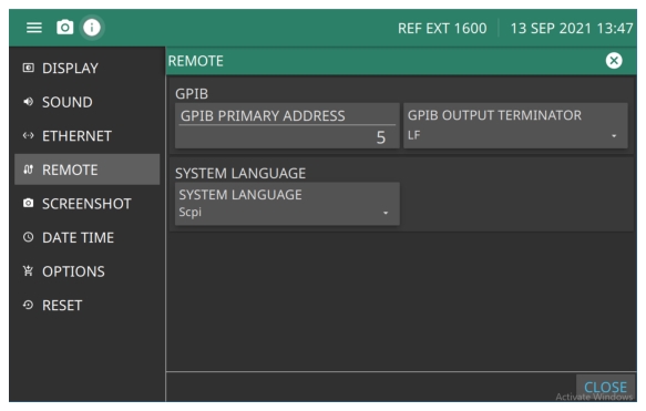
Configure GPIB Menu
GPIB
Select the address of the MG362x1A on the bus. Enter a new address, between one and 30. The new GPIB address will appear on the display.
GPIB OUTPUT TERMINATOR
select a carriage return (CR) or a carriage return and line feed (LF) or (CR/LF) as the GPIB data delimiter. Consult the GPIB controller's manual to determine which data delimiter is required.
SYSTEM LANGUAGE
Select SCPI Native or Tmsl ('Tmsl is an alias for SCPI). Entering either will return SCPI when queried.