The following tests verify that the power level accuracy and flatness of the MG362x1A meet specifications. Table: Power Level Accuracy Test Record and Table: Power Level Flatness Test Record contain test records that you can copy and use to record test results. These tests use an Anritsu ML243xA Power Meter with a MA247xD power sensor. If you use another power meter and power sensor, consult your product’s user guide for proper test setup and operation.
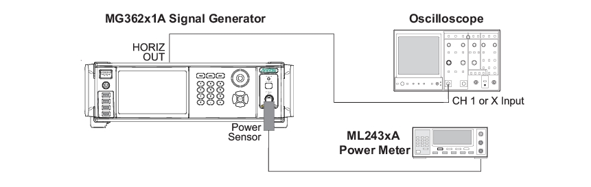
Equipment Setup for Power Level Accuracy and Flatness Tests
Caution
The MG362x1A is capable of output power levels in excess of +20 dBm. Ensure that proper care is taken to protect sensitive power sensors from being damaged by using a fixed attenuator. Do not apply power above +19 dBm to the power sensor.
b. Configure the power meter to perform power measurements by pressing:
Sensor | Setup | MODE | Default.
c. Configure the power sensor’s calibration factor source by pressing:
Sensor | CalFactor | SOURCE | V/GHz
until V/GHz is displayed.
d. Set up the minimum V/GHz range by pressing:
Setup | StartF
and enter the minimum frequency of the MG362x1A.
e. Set up the maximum V/GHz range by pressing:
Setup | StopF
and enter the maximum frequency of the MG362x1A.
f. Press any hard key to begin the measurement.
g. Calibrate the power meter with the power sensor.
2. Connect the power sensor to the RF Output of the MG362x1A (use a fixed attenuator when measuring power levels above +19 dBm).
3. Connect the special AUX I/O interface cable (Anritsu PN 806-97) to the MG362x1A rear panel AUX I/O connector. Connect the cable BNC connectors as follows:
a. Connect the cable labeled “SEQ SYNC” to the power meter rear panel INPUT 1 DIGITAL connector.
b. Connect the cable labeled “HORIZ OUT” to the power meter rear panel INPUT 2 ANALOG connector.