Two pulse modulation modes are available—Internal and External. In Internal mode, pulse modulation of the output signal is accomplished by using a modulating signal from the internal pulse generator. In External mode, pulse modulation of the output signal is achieved using a modulating signal from an external source.
The internal pulse generator has four pulse modes that include single, doublet (double pulse), triplet (triple pulse), and quadruplet (quadruple pulse). Individual pulse widths and delays can be set for each of the pulses in a mode. The pulse generator has a 100 MHz clock rate. The 100 MHz clock rate produces higher resolution pulses and allows higher PRFs. The clock rate command is available only for backward compatibility so it doesn't create a syntax error. It is not operationally functional.
The internal pulse generator can be internally triggered, externally triggered, internally and externally triggered with delay, and gated. There is also a composite trigger mode in which an external pulse is summed with the internal pulse to pulse modulate the output signal. Refer to the MG362x1A technical data sheet (11410-00928) for pulse period, pulse width, and pule delay specifications.
Internal Pulse Modulation Function
The IP command turns on the internal pulse modulation function. The internal pulse mode is selected using the PMD(x) command and the internal pulse trigger is selected using the PTG(x) command. The pulse period can be set using the PER parameter entry command; the pulse frequency can be set using the PR parameter entry command. Individual pulse widths can be set using the W1 (or PW) parameter entry commands. Individual pulse delays can be set using the D1 (or PDY) parameter entry commands. The P0 (or SW0) command turns off the pulse modulation function.
Square wave pulse modulation of the output signal by one of four internal modulating signals is available using the following commands:
Programming Example:
Programming “IP PMD1 PTG2 PER 1 MS W1 2.5 US D1 10 US” turns on the internal pulse modulation function; selects the doublet pulse mode, free run trigger mode, sets the pulse period to 1 ms, pulse width1 to 2.5 μs, and delay1 to 10 μs.
External Pulse Modulation Function
The XP command turns on the external pulse modulation function. The PO command turns off the pulse modulation function.
Modulation Command List
Modulation Command List (1 of 2)
Mnemonic Code
Function
AM0
Turns off the internal or external AM function.
AM1
Turns on the external AM function in Linear mode.
AM2
Turns on the external AM function in Log mode.
AM7
Turns on the internal AM function in Linear mode.
AM8
Turns on the internal AM function in Log mode.
AMO
Turns off the internal AM function generator if it is on.
AMW(x)
Selects the internal AM waveform, where x = 1-sine wave, 2-square wave, 3-positive ramp, 4-negative ramp, 5-Gaussian noise, 6-uniform noise, 7-triangle wave, 8-user defined.
AUT
Selects Sweep Trigger.
D1
Set the internal pulse delay1 parameter.
DPT
Internal triggered pulse with delay.
EP0
Selects TTL-low to turn RF on during pulse modulation.
EP1
Selects TTL-high to turn RF on during pulse modulation.
FM0
Turns off the internal or external FM function.
FM1
Turns on the external FM function in Unlocked Narrow mode.
FM2
Turns on the external FM function in Locked Low-Noise mode.
FM7
Turns on the internal FM function in Unlocked Narrow mode.
FM8
Turns on the internal FM function in Unlocked Wide mode.
FM9
Turns on the internal FM function in Locked mode.
FML
Turns on the external FM function in Locked mode.
FMN
Turns on the internal FM function in Locked Low-Noise mode.
FMU
Turns on the external FM function in Unlocked Narrow mode (Same as FM1).
FMW
Turns on the external FM function in Unlocked Wide mode.
FWV(x)
Selects the internal FM waveform, where x = 1-sine wave, 2-square wave, 3-positive ramp, 4-negative ramp, 5-Gaussian noise, 6-uniform noise, 7-triangle wave.
FWV1
Set sine wave as the modulating waveform.
FWV2
Set Gaussian wave as the modulating waveform.
FWV3
Set positive ramp wave as the modulating waveform.
FWV4
Set negative ramp wave as the modulating waveform.
FWV5
Set square wave as the modulating waveform.
FWV6
Set triangle wave as the modulating waveform.
FWV7
Set uniform noise wave as the modulating waveform.
GP
Internal gated pulse on.
IP
Turns on internal pulse modulation.
OFP
Outputs the current frequency preset.
OMPS
Output current pulse modulation state on or off
OPHHS
Set ΦM on or off.
PC1
PC4
Set the 100 MHz internal pulse clock rate.
PDY
Set the power delay parameter for D1
PER
Set the internal pulse period parameter.
PH0
Turns off the internal or external ΦM function.
PH1
Turns on the external ΦM function in Narrow mode.
PH2
Turns on the external ΦM function in Wide mode.
PH7
Turns on the internal ΦM function in Narrow mode.
PH8
Turns on the internal ΦM function in Wide mode.
PHN
Turns on the external ΦM function in Narrow mode (Same as PH1).
PHV1
Selects the internal ΦM waveform as sine wave.
PHV2
Selects the internal ΦM waveform as square wave.
PHV3
Selects the internal ΦM waveform as positive ramp.
PHV4
Selects the internal ΦM waveform as negative ramp,
PHV5
Selects the internal ΦM waveform as Gaussian noise.
PHV6
Selects the internal ΦM waveform as uniform noise.
PHV7
Selects the internal ΦM waveform as triangle wave.
PMD(x)
Selects the internal pulse mode, where x = 1-single, 2-doublet, 3-triplet, 4-quadruplet.
PTF
Selects internal pulse triggering on the falling edge of an external input. Active only when pulse trigger is gated, triggered, or triggered with delay.
PW
Set the internal pulse width 1 parameter.
P0
Turns off the internal or external pulse modulation function (This is the default mode).
PMD(x)
Selects the internal pulse mode, where x = 1-single, 2-doublet, 3-triplet, 4-quadruplet.
PTG(x)
Selects the internal pulse trigger, where x = 1-free run, 2-gated, 3-delayed, 4-triggered, 5-triggered with delay, 6-composite.
PTR
Selects internal pulse triggering on the rising edge of an external input. Active only when pulse trigger is gated, triggered, or triggered with delay.
SQP
Turns on internal 1 kHz square wave pulse modulation.
SW0
Turns off the internal or external pulse modulation function (Same as P0).
SW1
Turns on internal 400 Hz square wave pulse modulation.
SW2
Turns on internal 1 kHz square wave pulse modulation (Same as SQP).
SW3
Turns on internal 7.8125 kHz square wave pulse modulation.
SW4
Turns on internal 27.8 kHz square wave pulse modulation.
W1
Set the internal pulse width 1 parameter.
XP
Turns on the external pulse modulation function. Disables the internal pulse modulation function, if previously programmed.
Complex Modulation (Option 10)
The Option 10–Complex Modulation capability facilitates GPIB and Serial commands to prepare the instrument for receiving user defined waveform data. Waveform data transfer for a complex modulation waveform occurs following the GPIB or Serial command to prepare the synthesizer for receipt of the data. Once the synthesizer has received the command, it stores the next 65,536 values as the waveform data. If the waveform data comprises less than 65,536 values, the data is uniformly expanded to fill all 65,536 values. Refer to the Option 10 Complex Modulation User Guide for detailed information about waveform data and additional capabilites provided by the Complex Modulation software. Option 10 is required for these commands.
Complex Modulation Commands (1 of 2)
MNEMONIC CODE
FUNCTION
ALW (0x04a9)
Prepares the signal generator to receive an AM waveform. A 2-byte value indicating the size of the waveform (minus 1) and 2-byte values containing the waveform data must immediately follow the command. Each waveform value is a 16-bit, unsigned integer consisting of two bytes, the upper half of the value followed by the lower half of the value. The size of the waveform must be a power of 2.
AR0 (0x04b2)
Disable random waveform access of the AM waveform.
AR1 (0x04b3)
Enable random waveform access of the AM waveform.
FLW (0x04ab)
Prepares the signal generator to receive an FM waveform. A 2-byte value indicating the size of the waveform (minus 1) and 2-byte values containing the waveform data must immediately follow the command. Each waveform value is a 16-bit, unsigned integer consisting of two bytes, the upper half of the value followed by the lower half of the value. The size of the waveform must be a power of 2.
FMO (0x04ac)
Disconnect the internal FM/ΦM function generator from the FM circuitry (only connected to the rear panel).
FR0 (0x04b4)
Disable random waveform access of the FM waveform.
FR1 (0x04b5)
Enable random waveform access of the FM waveform.
PHO (0x04ae)
Disconnect the internal FM/ΦM function generator from the FM circuitry (only connected to the rear panel).
PLW (0x04ad)
Prepares the signal generator to receive a ΦM waveform. A 2-byte value indicating the size of the waveform (minus 1) and 2-byte values containing the waveform data must immediately follow the command. Each waveform value is a 16-bit, unsigned integer consisting of two bytes, the upper half of the value followed by the lower half of the value. The size of the waveform must be a power of 2.
PMR0 (0x04b6)
Disable random waveform access of the ΦM waveform.
PMR1(0x04b7)
Enable random waveform access of the ΦM waveform.
SR0 (0x04b9)
Disable synchronization of the AM and FM/ΦM randomizers. Note: The SR0 or SR1 commands should be sent before the WFS and waveform data are sent to the signal generator. The commands will not function properly if not sent in the correct order.
SR1 (0x04ba)
Enable synchronization of the AM and FM/ΦM randomizers. Note: The SR0 or SR1 commands should be sent before the WFS and waveform data are sent to the signal generator. The commands will not function properly if not sent in the correct order.
WFS (0x04b8)
Enable synchronization of the internal AM and FM/ΦM function generators.
Note: The WFS command must be sent before and after any waveform as shown in the following example: WFS ALW<2-byte binary data for waveform size><2-byte binary data for waveform data> PLW<2-byte binary data for waveform size><2-byte binary data for waveform data> WFS
0x04af
Exit serial remote mode. Must be sent when serial communications are completed. This is a serial-only command.
0x04b0
Set signal generator serial port to 9600 baud. This is the default setting. This is a serial-only command.
0x04b1
Set signal generator serial port to 19200 baud. This is a serial-only command.
• The actual modulation depth of the RF output signal, as caused by an external AM signal connected to the rear panel AM IN connector.
• The actual frequency deviation of the RF output signal, as caused by an external FM signal connected to the rear panel FM IN connector.
• The actual RF power of an external source, via a 560-7, 5400-71, or 6400-71 series detector connected to the rear panel POWER METER connector (Option 8 is required).
Measure Function Commands
Mnemonic Code
Function
AMI
Turns on the AM Measurement mode.
FMD
Turns on the FM Measurement mode.
MOM
Turns off the AM and FM measurement modes.
Table: Output Commands (1 of 4) lists the output command mnemonic codes. These commands provide for the output of data from the CW generator to the controller is enabled and detected.
Output Commands (1 of 4)
Mnemonic Code
Function
*IDN?
Requests device identification.
OEM
Returns the Extended SRQ Mask bytes (3 binary bytes) to the controller.
OES
Returns the GPIB Status bytes (3 binary bytes, no terminator) to the controller.
OPP
Returns the internal pulse period value (in µs) to the controller.
OSB
Each Primary byte status reporting bit returns the primary GPIB Status byte (1 binary byte, no terminator) to the controller. Each extended status reporting bit is enabled and detected.
OSR
Returns the self-test results (6 binary bytes, no terminator) to the controller.
Table: SRQ and Status Byte Commands (1 of 2) lists the Service Request (SRQ) and Status Byte command mnemonic codes. These commands enable the signal generator to request service from the controller when certain, predefined conditions exist.
•
SRQ Generation
The signal generator can generate GPIB service requests (SRQs) to report instrument status and syntax errors to the controller. The signal generator will generate an SRQ if:
1. The SRQ generation function has been enabled using the SQ1 command and,
2. One (or more) of the status reporting functions is true and,
3. The primary status byte bit associated with the true status reporting function has been enabled.
Bits in the primary status byte can be enabled by either of two methods. The first uses the FB1/FB0, UL1/UL0, LE1/LE0, and SE1/SE0 commands.individually enable or disable each bit. The second method uses a single 8-bit status byte mask (MB0) to enable any or all of the primary status byte bits.
Primary and Extended Status Bytes
Note
All status byte bits are latched except for those indicated with the “*”. Once set, an OES or OSB command must be received before the condition will be reset. The primary status byte bit 6 (SRQ) is cleared by a serial poll only.
Primary Status Byte
Extended Status Byte 2
SRQ
Syntax Error
Parameter Range Error
Lock Error
RF Unleveled
Not Used
Extended Status Byte 1
Bit 7 (128)
Bit 6 (64)
Bit 5 (32)
Bit 4 (16)
Bit 3 (8)
Bit 2 (4)
Bit 1 (2)
Bit 0 (1)
Primary status byte bit 0 is set whenever one of the status conditions reported by an extended status byte 1 is true and the associated status bit is enabled. This bit is cleared when the controller sends the OES command.
Primary status byte bit 7 is set whenever one of the status conditions reported by an extended status byte 2 is true and the associated status bit is enabled. This bit is cleared when the controller sends the OES command.
Primary status byte bit 6 (SRQ) is not maskable. This bit is enabled by the SQ1 command and cleared by a serial poll.
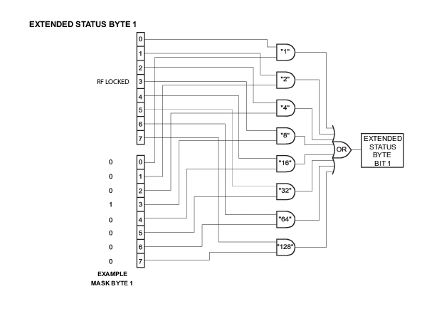
Extended Status Byte 1
Not Used
Not Used
Not Used
Not Used
RF* Locked
Not Used
Not Used
Not Used
Bit 7 (128)
Bit 6 (64)
Bit 5 (32)
Bit 4 (16)
Bit 3 (8)
Bit 2 (4)
Bit 1 (2)
Bit 0 (1)
Extended status byte 1 bits are enabled by the extended status byte 1 mask command, MB1.
Extended status byte 1 bit 3 (RF Locked): the setting of this bit is blocked or unblocked by the commands, LS0 and LS1.
Extended Status Byte 2
Not Used
Not Used
Not Used
RF* Unlocked
Not Used
Not Used
Not Used
Not Used
Bit 7 (128)
Bit 6 (64)
Bit 5 (32)
Bit 4 (16)
Bit 3 (8)
Bit 2 (4)
Bit 1 (2)
Bit 0 (1)
Extended status byte 2 bits are enabled by the extended status byte 2 mask command, MB2.
The setting of extended status byte 2 bit 4 (RF Unlocked) is blocked or unblocked by the commands, EL0 and EL1.
SRQ and Status Byte Commands (1 of 2)
Mnemonic Code
Function
CSB
Clears all Native status bytes.
EL0
Inhibits the RF Unlocked bit update. ESB2 bit 4.
EL1
Enables the RF Unlocked bit update. ESB2 bit 4.
FB0
Inhibits Extended Status Byte 1 SRQ generation. Primary byte bit 0.
FB1
Enables Extended Status Byte 1 SRQ generation. Primary byte bit 0.
LE0
Inhibits Lock Error SRQ generation. Primary byte bit 3.
LE1
Enables Lock Error SRQ generation. Primary byte bit 3.
LS0
Inhibits RF Locked bit update. ESB1 bit 3.
LS1
Enables RF Locked bit update. ESB1 bit 3.
MB0
Sets the enable mask byte for the Primary Status Byte.
MB1
Sets the enable mask byte for Extended Status Byte 1.
MB2
Sets the enable mask byte for Extended Status Byte 2.
OEM
Returns the Extended SRQ Mask bytes (3 binary bytes) to the controller.
OES
Returns the GPIB Status bytes (3 binary bytes) to the controller.
OSB
Returns the Primary GPIB Status byte to the controller.
OSM
Returns the Primary SRQ Mask byte to the controller.
PE0
Inhibits Parameter Range Error SRQ generation. Primary byte bit 4.
PE1
Enables Parameter Range Error SRQ generation. Primary byte bit 4.
SB0
Inhibits Extended Status Byte 2 SRQ generation. Primary byte bit 7.
SB1
Enables Extended Status Byte 2 SRQ generation. Primary byte bit 7.
SQ0
Disables the SRQ generation function when a Primary byte bit is set.
SQ1
Enables SRQ generation when a Primary byte bit is enabled.
UL0
Inhibits RF Unleveled SRQ generation. Primary byte bit 2.
UL1
Enables RF Unleveled SRQ generation. Primary byte bit 2.
The MG362x1A has a software mask that permits manipulation of the three status bytes over the bus that are accomplished by sending the command codes MB0, MB1, MB2, or all three at once, followed by an argument that assigns an on/off condition for each bit in the byte. A status byte example is shown in Figure: Status Byte Example.
Status Byte Example
Example:MB1\x08
MB1 should be followed by a single binary byte. This example uses the hexadecimal escape sequence "\x08" to represent a single byte with value 0x08. Enables bit 3 in extended status byte 1. Same as the LS1 command.
Table: Self Test Command lists the self test command mnemonic code. This command provides for executing a signal generator self test.
When a TST command is received, the signal generator performs a self test, then returns a single byte, unterminated. A "P" (for pass) or an "F" (for fail). It also generates six self test results bytes.
Self Test Command
Mnemonic Code
Function
TST
Executes a signal generator self test. Extended Status Byte 1 bit 0 is set if self test fails; bit 2 is set when self test is complete.
OSR
Returns the six self test results bytes to the controller.
Refer to Self-Test Messages for the self.test error and messages descriptions. The “P or “F” character placed on the bus by the signal generator self test must be cleared from the output buffer (read by the controller) before another output command, such as OSR, is sent. If it is not cleared, the first character of the next output will be missing.
Self Test Results
The six self test results bytes that identify the reporting function of each bit is shown below.
Self Test Results Byte 1
Not Used
Not Used
Power Supply Voltage(s) are Out of Reg
Not Used
Not Used
Not Used
Not Used
Not Used
Bit 7 (128)
Bit 6 (64)
Bit 5 (32)
Bit 4 (16)
Bit 3 (8)
Bit 2 (4)
Bit 1 (2)
Bit 0 (1)
Self Test Results Byte 2
Not Used
Not Used
Not Used
Not Used
Not Used
Not Used
Not Used
Not Used
Bit 7 (128)
Bit 6 (64)
Bit 5 (32)
Bit 4 (16)
Bit 3 (8)
Bit 2 (4)
Bit 1 (2)
Bit 0 (1)
Self Test Results Byte 3
Not Used
Not Used
Not Used
Not Used
Not Used
Not Used
Not Used
Not Used
Bit 7 (128)
Bit 6 (64)
Bit 5 (32)
Bit 4 (16)
Bit 3 (8)
Bit 2 (4)
Bit 1 (2)
Bit 0 (1)
Self Test Results Byte 4
Not Used
Not Used
Switch Filter Failed
Not Used
Not Used
Not Used
Not Used
Not Used
Bit 7 (128)
Bit 6 (64)
Bit 5 (32)
Bit 4 (16)
Bit 3 (8)
Bit 2 (4)
Bit 1 (2)
Bit 0 (1)
Self Test Results Byte 5
Not Used
Frequency Extension Module (FEM) Failed
Not Used
Not Used
Mod Processor Failed
Not Used
Not Used
Not Used
Bit 7 (128)
Bit 6 (64)
Bit 5 (32)
Bit 4 (16)
Bit 3 (8)
Bit 2 (4)
Bit 1 (2)
Bit 0 (1)
Self Test Results Byte 6
Self Test is Complete
Not Used
Not Used
RF Was Off When Self Test Started
Not Used
Not Used
Not Used
Not Used
Bit 7 (128)
Bit 6 (64)
Bit 5 (32)
Bit 4 (16)
Bit 3 (8)
Bit 2 (4)
Bit 1 (2)
Bit 0 (1)
Self Test Example
This code demonstrates synchronous read and write commands to a Socket instrument using VISA to perform and return self test results.