Rubidium™ MG362x1A Series Low-Noise RF/Microwave Signal Generator User Guide : Instrument Operation : Markers Menu
 
Markers Menu
Markers are available with Option 6. The signal generator provides ten independent, pre-settable markers, M0-M9, that can be used in the step sweep and analog frequency mode for precise frequency identification. Marker frequency accuracy is the same as sweep frequency accuracy. The markers are visible on a monitor display.
MARKERS Menu
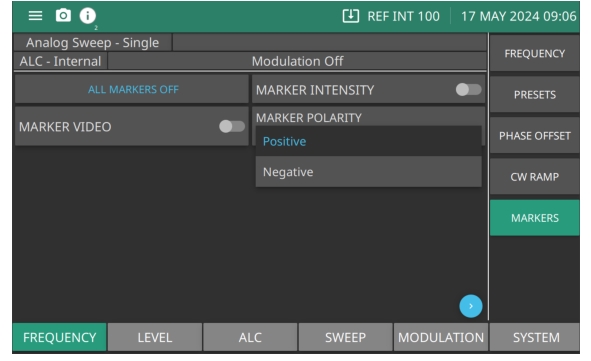
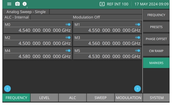
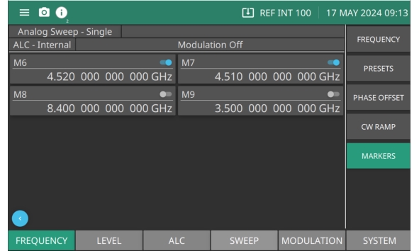
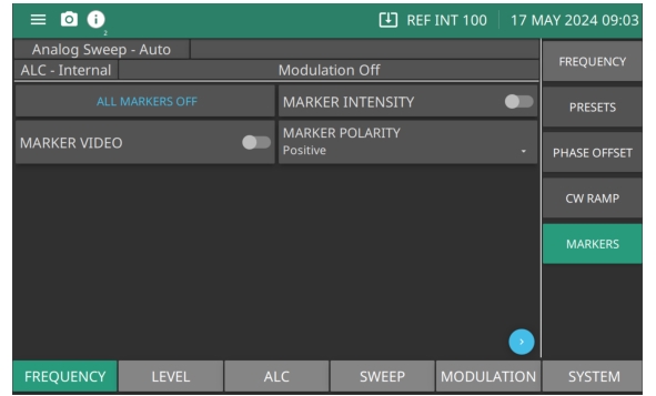
ALL MARKERS OFF
Press to turn off all markers.
MARKER INTENSITY
Produces an intensified dot on the display at each marker frequency. They are obtained by a momentary dwell in the sweep at each marker frequency. Intensity markers are only available in the analog sweep frequency mode at sweep times of < 1 second. To output markers during a sweep you must first select (tag) the marker frequencies.
MARKER VIDEO
Produces a pulse on the display at each marker frequency.
MARKER POLARITY
Provides the a +5 V or a –5 V pulse. Set polarity as shown in Figure: MARKER POLARITY.
 
Marker Polarity
Press MARKER POLARITY and then press Positive or Negative to set the markers polarity on the signal display as positive or negative. All active markers on the display are set.
MARKER POLARITY
SET MARKERS
Use the blue arrows shown in Figure: Set Markers to scroll the page right or left. Press M(x) to set a marker frequency location on the display. Toggle the switch to the “on” position to see the marker. Set any number of markers to be displayed on the monitored signal. Press the blue arrow on the right to scroll to the second page where markers M6 through M9 are available to set as shown in Figure: Markers - Page Two.
Set Markers
Markers - Page Two