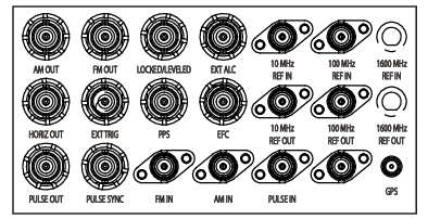
Provides the amplitude modulation waveform from the internal LF generator. Enabled with Option 027. (BNC type, rear panel)
HORIZ OUT
Provides 0 V at beginning and +10 V at end of sweep, regardless of sweep width. In CW mode, the voltage is proportional to frequency between 0 V at low end and +10 V at the high end of the range. In CW mode, if CW RAMP is enabled, a repetitive, 0 V to +10 V ramp is provided.(BNC type, rear panel)
PULSE OUT
Provides a video modulating signal from the internal pulse generator. Enabled with Option 027. (BNC type, rear panel)
FM OUT
Provides the frequency or phase modulation waveform from the internal LF generator. Enabled with Option 027. (BNC type, rear panel)
EXT TRIG
Accepts a TTL low-level signal of 1 μs width to trigger a sweep. (BNC type, rear panel)
PULSE SYNC
Provides a TTL compatible signal, synchronized to the internal pulse modulation output. Enabled with Option 026. (BNC type, rear panel)
LOCKED/LEVELED
TTL high/low output signal when in internal ALC mode that is a logical AND of frequency locked condition and output leveled condition. When in Fixed Gain mode this signal indicates only frequency locked/unlocked condition. (BNC type, rear panel)
PPS
1PPS input/output from either GNSS atomic clock receiver or internal rubidium reference option. (3.3V CMOS I/O, BNC type, rear panel)
FM IN
Accepts an external signal to frequency or phase modulate the RF output signal. Enabled with Option 012. 50 Ω impedance. (BNC type, rear panel)
EXT ALC
Provides for leveling the RF output signal externally with either a detector or power meter. Signal requirements are shown in the RF Output specifications. (BNC type, rear panel)
EFC
±4 VDC 30 Hz bandwidth in wide reference PLL mode 1 MΩ input impedance. Provides the capability to frequency modulate the internal crystal oscillator, allowing phase locking of the synthesizer inside an external lock loop. (BNC type, rear panel)
AM IN
Accepts an external signal to amplitude modulate the RF output signal. Enabled with Option 012. 50 Ω impedance. (BNC type, rear panel)
10 MHZ REF IN
Accepts an external 10 MHz ± 3 Hz, 0 dBm to +10 dBm (20 dBm no-damage level) time-base signal. Automatically disconnects the internal high-stability time-base option, if connected. 50 Ω impedance input (BNC type, rear panel)
10 MHZ REF OUT
Provides a 10 dBm, AC coupled, signal derived from the internal frequency standard. 50 Ω impedance, SMA type, rear panel
PULSE IN
Accepts an external TTL compatible signal to pulse modulate the RF output signal or to trigger or to gate the optional internal pulse generator. Enabled with Option 026. (BNC type, rear panel)
100 MHZ REF IN
Accepts an external 100 MHz ± 200 Hz or 2 ppm 12 ± 1 dBm (20 dBm no-damage level) reference signal. Enabled with Option 003 or 013. Automatically disconnects the internal high-stability time-base option, if connected. (50 Ω impedance, SMA type, rear panel
100 MHZ REF OUT
Provides a 12 dBm, AC coupled, 100 MHz signal derived from the internal frequency standard. Enabled with Option 003 or 013. (50 Ω impedance, SMA type, rear panel
1600 MHZ REF IN
Accepts an external 1600 MHz ± 3.2 kHz or 2 ppm, 4 ± 1 dBm (20 dBm no-damage level) reference signal. Enabled with Option 003 or 013. Automatically disconnects the internal high-stability time-base option, if connected. (50 Ω impedance, SMA type, rear panel
1600 MHZ OUT
Provides a 5 dBm, AC coupled, 1600 MHz signal derived from the internal frequency standard. Enabled with Option 003 or 013. (50 Ω impedance, SMA type, rear panel