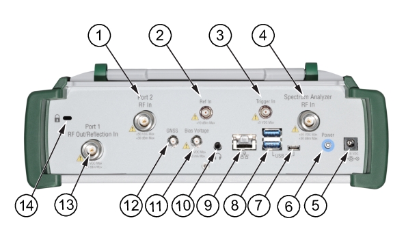
The MS2085A/89A Site Master uses the top connector panel to provide for all physical IO. The top panel uses a variety of connector types intended for their purpose.
RF Connectors
The main RF connectors are Type N 50 Ω female connectors. Note that RF connectors can be input and output connectors depending on your instrument model. Additional IO is provided with the SMA style connectors. The SMA connectors are also 50 Ω female. Refer to instrument technical data sheet for connector information.
Caution
To prevent damage to your instrument, do not use pliers or a plain wrench to tighten the connectors. Do not overtighten the connector. The recommended torque for Type N is 12 lbf·in (1.35 N·m or 135 N·cm).
The external reference input port is a 50 Ω SMA connector that provides for input of an external frequency reference. Re
2. Ref In
The external reference input port is a 50 Ω SMA connector that provides for input of an external frequency reference. Refer to your Technical Data Sheet for valid frequencies. The instrument automatically selects the frequency reference in the following order of priority: external, GNSS (GPS), then the internal time base. To prevent damage to your instrument, do not use pliers or a wrench to tighten the connector.
3.Trigger In
A TTL signal that is applied to the external trigger 50 Ω SMA input connector causes a single sweep to occur. In spectrum analysis, triggering is generally used in zero span, and triggering occurs on the rising edge of the signal. After the sweep is complete, the resultant trace is displayed until the next trigger signal arrives. To prevent damage to your instrument, do not use pliers or a wrench to tighten the connector.
4. SPA RF In
This is a 50 Ω Type N female ruggedized connector.
Maximum Input: ±50 VDC, +30 dBm, +13 dBm with Preamp On
To prevent damage to your instrument, do not try to mate incorrect connector types or use pliers or a plain wrench to tighten the connector. Do not overtighten the connector. The recommended torque for Type N is 12 lbf·in (1.35 N·m or 135 N·cm).
5. External Power
This is a 2.5 mm by 5.5 mm barrel connector, 15 VDC, 5 A, center positive. The external power connector is used to power the unit and for battery charging.
Warning
When using the AC-DC Adapter, always use a three-wire power cable that is connected to a three-wire power line outlet. If power is supplied without grounding the equipment in this manner, the user is at risk of receiving a severe or fatal electric shock.
The Site Master MS2085A/89A has one Type C USB connector on the top panel. The USB Type-C port is used to connect the Site Master directly to a PC and provides a remote SCPI programming interface via USBTMC (USB Test and Measurement Class). Refer to the MS2085A/89A programming manual for remote SCPI control setup and command.
8. USB Interface – Type A
The Site Master MS2085A/89A has two Type A and one Type C USB connectors that accept USB storage devices for saving measurements, setup data, and screen images. They are located on the top panel. To ensure the device or its data does not become corrupted, Select the eject icon to eject (unmount) the USB device before it is unplugged from the USB port (see Title Bar).
Note
The MS2085A/89A is compatible with external USB memory devices that have an integrated keypad and are FIPS compliant using AES 256-bit encryption.
9. LAN Connection
The RJ‑45 connector is used to connect the Site Master to a local area network or directly to a PC with an Ethernet crossover cable. See Ethernet Connection for more details.
10. Headset Jack
The 3‑wire headset jack provides audio output from the built‑in sounds generated by the instrument. The jack accepts a 3.5 mm 3‑wire miniature phone plug such as those commonly used with cellular telephones.
11. Bias Voltage
The bias voltage output port is a 50 Ω SMA connector. The power supply is set up to provide 1 V to 34 V with a resolution of 0.1 V. The maximum current is 500mA, but with at total maximum power of 15 W. To prevent damage to your instrument, do not use pliers or a wrench to tighten the connector.
12. GNSS Antenna Connector
The GNSS antenna connection on the Site Master is type SMA female. This connector also provides 5.0/3.3 VDC for an active GNSS antenna. To prevent damage to your instrument, do not use pliers or a wrench to tighten the connector.
13. Port 1 RF out/Reflection In
RF input and output, 50 Ω Type-N female connector, for reflection measurements. The maximum input is +30 dBm at ±50 VDC.
14. Kensington® Lock (K-slot)
Provides a slot that accepts Kensington style cable locks.