 |
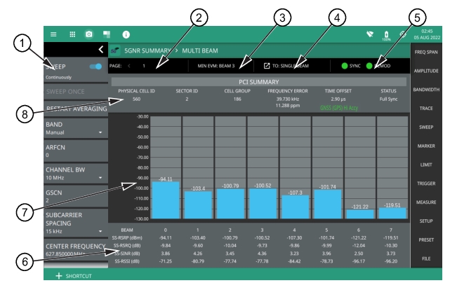
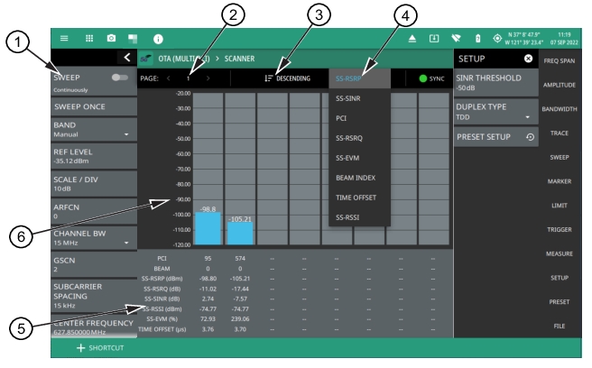
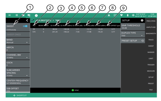
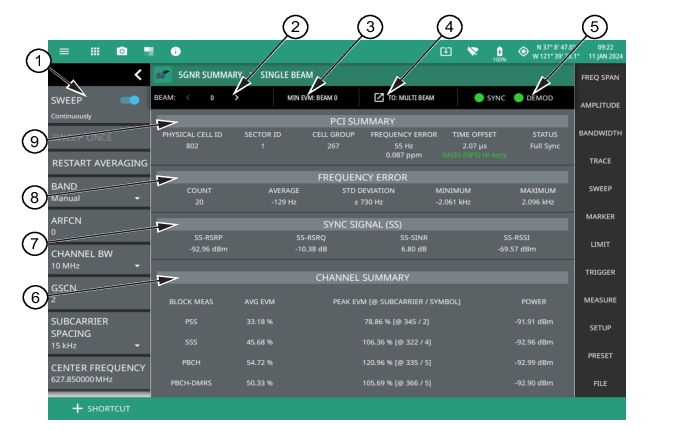
1. 5GNR Analyzer Status Panel: Each measurement features a unique status panel that displays settings and information relevant to the current measurement and view settings. This panel provides quick access to the measurement frequency, subcarrier spacing, channel bandwidth, and band configuration. See Status Panel (5GNR Summary). 2. BEAM: This field indicates the current beam summary page. A maximum of 64 beams (numbered 0 to 63) can be individually displayed in single beam view. You can cycle through the beam pages using the left/right (</>) arrows or touch the number to select the desired beam. 3. MIN EVM BEAM: This field shows which beam measures lowest error vector magnitude (EVM). 4. SINGLE/MULTI BEAM: This field shows the current view setting. Touch this field to toggle between SINGLE BEAM or MULTI BEAM views. You can also change the view setting from the MEASURE menu. 5. SYNC/DEMOD: Valid 5GNR measurements require the signal synchronization and demodulation. The indicators here blink green when the received signal is synchronized and properly demodulated, indicating that you have a valid measurement. 6. Channel Summary: For the current beam, shows the average error vector magnitude (EVM), peak EVM (@ subcarrier/symbol) and received power in dBm for each block measurement: • PSS: The primary synchronization signal provides the primary frame boundary (i.e., the position of the first symbol in the frame). • SSS: Similar to PSS, the secondary synchronization signal provides the secondary sub-frame boundary. • PBCH: This is the physical broadcast channel, the main purpose of which is to carry the broadcast information block. • PBCH-DMRS: In 5GNR measurements, the PBCH decoding relies on a demodulation reference signal (DMRS, which is a physical layer reference signal used for decoding) rather than a cell specific reference signal (CRC). 7. Sync Signal (SS) Summary Data: Shows the following synchronization signal summary data for the current beam: • SS-RSRP: Secondary synchronization signal reference signal received power measured in dBm. • SS-RSRQ: Secondary synchronization signal reference signal received quality measured in dB. • SS-SINR: Secondary synchronization signal-to-noise and interference ratio measured in dB. • SS-RSSI: Secondary synchronization signal reference signal received indicator measured in dBm. 8. Frequency Error: This section shows the frequency error of all the measured signals. It is the difference between the measured carrier frequency and the specified carrier frequency. This measurement is only as accurate as the frequency reference that is used and is typically only useful with a good external frequency reference or GNSS (GPS). It consists of the following data: • Count: The total number of frequency measurements included in the averaging measurement. • Average: The average value of all frequency measurements made. • Standard Deviation: The measure of the spread of frequency measurements. The standard deviation is the average difference of all measurements from the average frequency measurement. Typically 68% of all measurements will fall within the standard deviation value shown. • Minimum: The single lowest frequency value measured. • Maximum: The single highest frequency value measured. 9. PCI Summary: This section shows the physical cell ID summary data, including the sector ID, cell group number, frequency error, time offset, and sync status. Sync status can indicate if there is a PSS, SSS, or Beam Index failure, Full Sync, or an Unknown condition. Also noted is the instrument’s reference clock accuracy of Internal, External, or GNSS (GPS) high accuracy (requires GPS |