5GNR Analyzer Measurement Guide : 5GNR Analyzer (Option 888) : 5GNR Carrier Aggregation
 
5GNR Carrier Aggregation
To select carrier aggregation measurement go to main menu and press MEASURE > MEASUREMENT >Carrier Aggregation. The carrier aggregation measurements are set up using the SETUP Menu (5GNR Carrier Aggregation). 5GNR carrier aggregation measurements are used for compliance testing of 5GNR networks and can evaluate active antenna systems for dynamic physical layer attributes and received power levels of the transmitted signal.
5GNR Carrier Aggregation View
Carrier aggregation displays up to eight component carrier (CC) measurements. Each carrier can be set up uniquely for signal band. An example 5GNR carrier aggregation measurement is shown in Figure: 5GNR Carrier Aggregation.
5GNR Carrier Aggregation
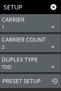
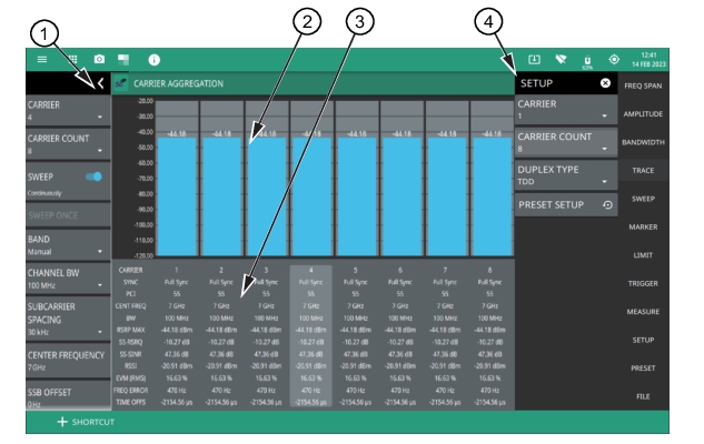
1. 5GNR Analyzer Status Panel: Each measurement features a unique status panel that displays settings and information relevant to the current measurement and view settings. This panel provides quick access to the measurement frequency, subcarrier spacing, channel bandwidth, and band configuration. See Status Panel (5GNR Carrier Aggregation).
2. Signal Level: This area shows a bar graph of the RSRP of the SSB beam with the lowest detected EVM.
3. Summary Display: Shows data for each numbered component carrier. The highlighted summary display area is the component carrier data that can be edited, and this area can be touched to select that component carrier for editing. A rotating magenta circle indicates which carrier is currently being measured.
Sync status indicating primary synchronization signal (PSS) full synchronization or PSS failure.
Physical Cell ID (PCI) identifying information sent by the transmitter in the sync signal.
Center frequency of the measurement channel.
Channel bandwidth (BW) sets the bandwidth of the component carrier.
Reference Signal Received Power (RSRP) max power is displayed in dBm. The reference signal is used for downlink channel estimation.
SS-RSRP indicates the average power received from a single Reference signal or the level of the received signal from the base station.
SS-RSRQ indicates the quality of the received signal.
SS-SINR indicates the ratio of the signal level to the noise level. Higher the value, the better is the signal quality.
EVM (RMS) shows the percentage value of all the error vectors between the reconstructed ideal signals and the received signals divided by the RMS value of the ideal signals.
Frequency error is the difference between the measured carrier frequency and the specified carrier frequency. This measurement is only as accurate as the frequency reference that is used and is typically only useful with a good external frequency reference or GNSS (GPS).
Time offset shows the time difference between the measured start of the 5GNR frame and the 10 ms frame trigger, which is automatically synchronized to GNSS (GPS) when the instrument has GNSS (GPS) lock.
4. SETUP Menu: The component carrier settings are configured in the SETUP menu. See SETUP Menu (5GNR Carrier Aggregation).
SETUP Menu (5GNR Carrier Aggregation)
The carrier aggregation SETUP menu is available in MEASURE > MEASUREMENT > Carrier Aggregation > SETUP.
5GNR SETUP Menu (Carrier Aggregation)
-
 
CARRIER
Selects the component carrier to make active. The active carrier is highlighted in the summary display area.
CARRIER COUNT
Sets the number of carriers to be displayed on the screen and to be measured.
DUPLEX TYPE
Selects either frequency division duplex (FDD) or time division duplex (TDD).
PRESET SETUP
Presets the SETUP menu to default settings.
 
Status Panel (5GNR Carrier Aggregation)
The status panel illustrated in this section is unique to the current analyzer and to the particular measurement and view that is selected.
Figure: Status Panel (5GNR Carrier Aggregation Measurement) shows the 5GNR status panel that covers the 5GNR carrier aggregation measurement.
 
Status Panel (5GNR Carrier Aggregation Measurement) 
 
CARRIER
Selects the component carrier to make active. The active carrier is highlighted in the summary display area.
CARRIER COUNT
Sets the number of carriers to be displayed on the screen and to be measured.
SWEEP: Toggles the current sweep setting between continuously or sweep once.
SWEEP ONCE
When sweep is set to single sweep, SWEEP ONCE updates the measurement display. Data continues to be captured in the background.
BAND
Select MANUAL, GLOBAL ALL or one of the predefined bands. Selecting MANUAL hides ARFCN and GSCN settings. Selecting a predefined band or GLOBAL ALL activates ARFCN and GSCN settings.
REF LEVEL
The reference level is the top graticule line to the left on the measurement display.
SCALE/DIV
The scale can be set from 1 dB per division to 15 dB per division. The default setting is 10 dB. Selecting the plus (+) or minus (–) control changes the value by 1. SCALE/DIV is not available when linear y-axis amplitude units are selected.
CHANNEL BW
Sets the measurement channel bandwidth. The available bandwidth settings depend on the selected band and bandwidth option installed in the instrument. Refer to “Options Settings” section in Instrument Overview chapter of user guide.
SUBCARRIER SPACING
Sets the subcarrier spacing. The available input range is dependent on the selected band.
CENTER FREQUENCY
When the band is set to MANUAL, sets the center frequency of the measurement channel. Changing the center frequency sets the band to MANUAL.
SSB OFFSET
SSB is the Synchronous Signal Block. The SSB Offset sets the frequency offset between the SSB and the overall resource block.
FREQ REFERENCE
Indicates the current frequency reference source of Internal, External, or GNSS (GPS) Hi Accuracy (requires GPS). The instrument automatically selects the frequency reference in the following order of priority: external, GPS, then the internal time base.