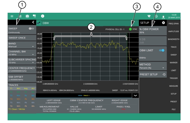
SWEEP: Toggles the current sweep setting between continuously or sweep once. SWEEP ONCE When sweep is set to single sweep, SWEEP ONCE updates the measurement display. Data continues to be captured in the background. BAND Select MANUAL, GLOBAL ALL or one of the predefined bands. Selecting MANUAL hides ARFCN and GSCN settings. Selecting a predefined band or GLOBAL ALL activates ARFCN and GSCN settings. REF LEVEL The reference level is the top graticule line to the left on the measurement display. If the reference level offset is not zero, the offset reference level is displayed at this location. Selecting the plus (+) or minus (–) control increments the value by 10. The plus/minus (+/-) button on the keypad toggles between positive and negative values. SECOND REF LEVEL The reference level is the top graticule line to the right on the measurement display. Its functionality is exactly same as reference level, but it is only available when trace math is enabled CHANNEL BW Sets the measurement channel bandwidth. The available bandwidth settings depend on the selected band and bandwidth option installed in the instrument. Refer to “Options Settings” section in Instrument Overview chapter of the user guide. SCALE/DIV The scale can be set from 1 dB per division to 15 dB per division. The default setting is 10 dB. Selecting the plus (+) or minus (–) control changes the value by 1. SCALE/DIV is not available when linear y-axis amplitude units are selected. SECOND SCALE/DIV It applies to second reference level and is available only when trace math is enabled. SUBCARRIER SPACING Sets the subcarrier spacing. The available input range is dependent on the selected band. CENTER FREQUENCY When the band is set to MANUAL, sets the center frequency of the measurement channel. Changing the center frequency sets the band to MANUAL. SSB OFFSET SSB is the Synchronous Signal Block. The SSB Offset sets the frequency offset between the SSB and the overall resource block. AUTO ATTEN Input attenuation can be either tied to the reference level (on) or manually selected (off). When input attenuation is tied to the reference level, attenuation is increased as higher reference levels are selected to make sure the instrument input circuits are not saturated by large signals that are likely to be present when high reference levels are required. ATTEN LEVEL When auto attenuation is off, the attenuation value can be set manually to a resolution of 5 dB. Selecting the plus (+) or minus (–) control increments the value by 10. TRACES: Displays the current status of up to six traces in a quick-view summary. The summary information includes the trace number, type, mode, and detector type. The active trace or cursor will show a highlighted background with the mode and detector type restated under the table. Touching a trace in the summary panel opens the TRACE menu. It allows you to select and set up an individual trace as desired. FREQ REFERENCE Indicates the current frequency reference source of Internal, External, or GNSS (GPS) Hi Accuracy (requires GPS). The instrument automatically selects the frequency reference in the following order of priority: external, GPS, then the internal time base. |