5GNR Analyzer Measurement Guide : 5GNR Analyzer (Option 888) : 5GNR Constellation
 
5GNR Constellation
To select constellation measurement go to main menu and press MEASURE > MEASUREMENT >Constellation. The constellation measurements are set up using the SETUP Menu (5GNR Constellation). 5GNR constellation measurement displays the demodulated symbol point location of a selected SSB beam on an IQ coordinate plot, which illustrates the constellation of a particular modulation format. The instrument displays QPSK constellation with a PCI summary and power tabular data. An example 5GNR constellation display and measurement is shown in Figure: 5GNR Constellation Measurement.
5GNR Constellation Measurement
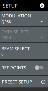
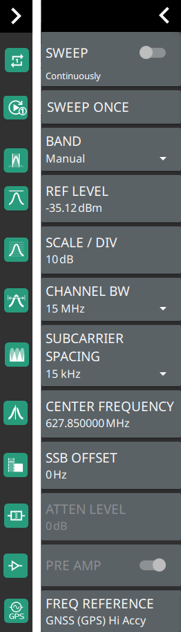
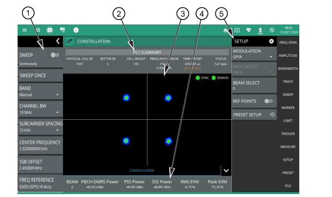
1. 5GNR Analyzer Status Panel: Each measurement features a unique status panel that displays settings and information relevant to the current measurement and view settings. This panel provides quick access to the measurement frequency, subcarrier spacing, channel bandwidth, and band configuration. See Status Panel (5GNR Constellation).
2. PCI Summary: This area shows the physical cell ID summary data, including the sector ID, cell group number, frequency error, time offset, and sync status. Sync status can indicate if there is a PSS, SSS, or Beam Index failure, Full Sync, or an Unknown condition. Also noted is the instrument’s reference clock accuracy of Internal, External, or GNSS (GPS) high accuracy (requires GPS).
3. Constellation: This area displays the demodulated symbol point location on an IQ coordinate plot. Points are drawn in colors that are associated with the symbol point density. Warmer colors (red/orange) indicate a higher symbol density where cooler colors (cyan/blue) indicate lower symbol density. The ideal symbol reference point location overlay can be toggled on or off via the SETUP menu.
4. Channel Summary: For the currently selected beam, shows the RMS error vector magnitude (EVM), peak EVM (@ subcarrier/symbol) and received power in dBm for each block measurement:
Beam: Shows the value of the selected 5GNR SSB beam.
PBCH-DMRS Power: In 5GNR measurements, the PBCH decoding relies on a demodulation reference signal (DMRS, which is a physical layer reference signal used for decoding) rather than a cell specific reference signal (CRC).
PSS Power: The primary synchronization signal provides the primary frame boundary
(i.e., the position of the first symbol in the frame).
SSS Power: Similar to PSS, the secondary synchronization signal provides the secondary sub-frame boundary.
RMS EVM: Shows the percentage value of all the error vectors between the reconstructed ideal signals and the received signals divided by the RMS value of the ideal signals.
Peak EVM: Shows the dominant cell’s peak EVM of all the error vectors between the reconstructed ideal signals and the received signals, divided by the RMS value of the ideal signals.
5. SETUP Menu: The constellation measurement settings are configured in the SETUP menu. See SETUP Menu (5GNR Constellation).
SETUP Menu (5GNR Constellation)
The control channel SETUP menu is available in MEASURE > MEASUREMENT > Constellation > SETUP.
SETUP Menu (5GNR Constellation)
-
 
 
MODULATION
Selects the modulation format (only QPSK is available).
DATA SELECT
Selects the data format (only Physical Broadcast Channel (PBCH) is available).
BEAM SELECT: Selects the 5GNR SSB beam for the demodulation and display. Minimum beam is 0 and Maximum is 63
REF POINTS
Toggles the ideal reference point locations on or off.
PRESET SETUP
Presets the SETUP menu to default settings.
 
Status Panel (5GNR Constellation)
The status panel illustrated in this section is unique to the current analyzer and to the particular measurement and view that is selected.
Figure: Status Panel (5GNR Constellation Measurement) shows the 5GNR status panel that covers the 5GNR constellation measurement.
 
Status Panel (5GNR Constellation Measurement) 
SWEEP
Toggles the current sweep setting between continuously or sweep once. Refer to Setting Sweep Parameters.
SWEEP ONCE
When sweep is set to single sweep, SWEEP ONCE updates the measurement display. Data continues to be captured in the background.
BAND
Select MANUAL, GLOBAL ALL or one of the predefined bands. Selecting MANUAL hides ARFCN and GSCN settings. Selecting a predefined band or GLOBAL ALL activates ARFCN and GSCN settings.
REF LEVEL
Sets the reference level of the top graticule line in the selected units. If the reference level offset is not zero, OFFSET REF LEVEL is displayed at this location. Refer to Setting Amplitude Parameters.
SCALE/DIV
Sets the graticule scale/division for log-based units. This setting does not apply to linear units.
CHANNEL BW
Sets the measurement channel bandwidth. The available bandwidth settings depend on the selected band and bandwidth option installed in the instrument. Refer to “Options Settings” section in Instrument Overview chapter of user guide.
SUBCARRIER SPACING
Sets the subcarrier spacing. The available input range is dependent on the selected band.
CENTER FREQUENCY
When the band is set to MANUAL, sets the center frequency of the measurement channel. Changing the center frequency sets the band to MANUAL.
SSB OFFSET
SSB is the Synchronous Signal Block. The SSB Offset sets the frequency offset between the SSB and the overall resource block.
ATTEN LEVEL
When auto attenuation is off, sets input attenuation.
PRE AMP
Toggles the low-noise front-end preamplifier on or off. Refer to Setting Amplitude Parameters.
TRACES
Displays the current status of up to six traces in the status panel. The trace card includes the trace number, type, mode, and detector type. The active trace will show a highlighted background with the mode and detector type restated under the table. Selecting a trace in the status panel activates the pressed trace and opens the TRACE menu, allowing you to select and set up an individual trace as desired. Refer to Setting Trace Parameters.
FREQ REFERENCE
Indicates the current frequency reference source of Internal High Accuracy (used after GPS has lost sync, but while the internal clock still has good GPS reference), Internal Standard Accuracy, External, or GNSS (GPS) Hi Accy (requires GPS). The instrument automatically selects the frequency reference in the following order of priority: external, GPS, then the internal time base.