5GNR Analyzer Measurement Guide : 5GNR Analyzer (Option 888) : 5GNR UL/DL Interference
 
5GNR UL/DL Interference
To select constellation measurement go to main menu and press MEASURE > MEASUREMENT >UL/DL Interference. The UL/DL constellation measurements are set up using the SETUP Menu (5GNR UL/DL Interference). 5GNR networks are typically TDD with time slots allocated to data transmission from the base station (Downlink) and data transmission from the user equipment (Uplink). The Uplink power is low relative to the Downlink power. Any Downlink signal that occurs in the Uplink timeslot will result in interference and reduced network performance. This can occur due to time delay from remote transmitters that arise due to atmospheric conditions as well as unaligned base station slot format settings. The Uplink interference measurement provides an insight into power in all frame slots helping to isolate the source of Uplink interference. See Figure: 5GNR UL/DL Interference TDD Measurement.
5GNR UL/DL Interference TDD Measurement

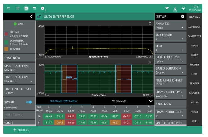
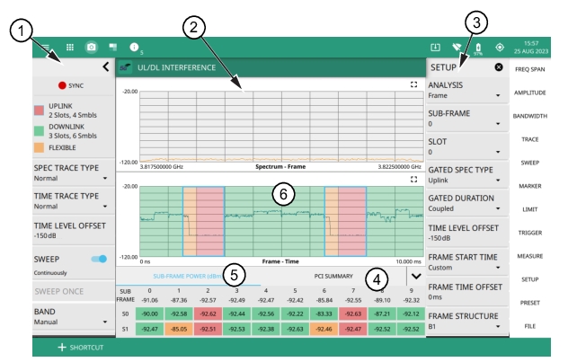
1. Status Panel: Each measurement features a unique status panel that displays settings and information relevant to the current measurement and view settings. This panel provides quick access to the measurement frequency and band configuration. See Status Panel (5GNR UL/DL Interference).
2. Gated Spectrum of Uplink/Downlink time slots: Shows trace data of the total frame, sub-frame or slot power measurement in the frequency domain.
3. SETUP Menu: The UL/DL Interference measurement settings are configured in the SETUP menu. See SETUP Menu (5GNR UL/DL Interference).
4. PCI SUMMARY: This area shows the physical cell ID, including the sector ID, cell group number, frequency error, time offset, sync status, and total frame power. Sync status can indicate if there is a PSS or SSS failure, a Full Sync, or an Unknown condition. Also noted is the instrument’s reference clock accuracy of Internal, External, or GNSS (GPS) high accuracy (requires GPS).
5. Sub-Frame Power Summary: This area shows the frame power measurement summary data. Power measurements are expressed in dBm.
The power of each subframe, each of two slots in the subframe, and the total frame power is measured.
6. UL/DL Interference vs. Time Display: Shows trace data of the total frame, sub-frame or slot power measurement in the time domain.
 
5GNR UL/DL Interference - Frame Structure

SETUP Menu (5GNR UL/DL Interference)
The UL/DL Interference SETUP menu is available in MEASURE > MEASUREMENT > UL/DL Interference > SETUP.
5GNR SETUP Menu (UL/DL Interference)
-
 
ANALYSIS
Selects the analysis time of full frame, subframe, or an individual slot. A single frame is 10 ms in duration and consists of 10 subframes (0 to 9).
SUB-FRAME
A single subframe is 1ms duration that is made up of one or more slots.
SLOT
A slot is a smaller time unit within a subframe that contains specific OFDM symbols.The length of a slot varies based on subcarrier spacing and the number of slots per subframe. A slot consists of 14 symbols.
GATED SPEC TYPE
Sets the gated spectrum type to Uplink, Downlink, Flexible, All or None. Note that in FDD, only All and None options are available.
GATED DURATION
Sets the gated duration to either Frame or Coupled. If Gated Duration is set to FRAME all the slots and symbols of the selected GATED SPEC TYPE in the entire frame is measured, whereas if it is set to Coupled all the slots and symbols of the selected GATED SPEC TYPE in the selected analysis subframe or slot period is measured.
TIME LEVEL OFFSET
Adjusts the time domain display reference level as an offset from the spectrum reference level. Sets the time level offset in the range from -150 dB to 150 dB.
FRAME START TIME
Choose frame start time from the list of available options:
Auto: Performs cell search and frame synchronization for every measurement.
Sync Once: Performs cell search once at the start to obtain frame start time to be used for successive frames.
UTC: UTC is Coordinated Universal Time. 3GPP specifications refer to UTC for network timing measurements. UTC and GNSS(GPS) time are both derived from the same atomic clocks and for the purposes of 3GPP network measurements can be used interchangeably.Represents a TDD start frame start time which corresponds with the coordinated universal time.
UTC+3 ms: Represents the frame start time which corresponds to UTC time plus 3 milli seconds.
UTC-2 ms: Represents the frame start time which corresponds to UTC time minus 2 milli seconds
Custom: Represents a custom frame time offset value that ranges from -5 ms to 5 ms.
SYNC NOW
Available when Frame Start Time is set to Sync Once. This forces a re-synchronization to obtain a frame start time to be used for successive frames.
FRAME STRUCTURE
Sets the frame setup parameters to a commonly used configuration. Selects either A, B1, B2 or Custom, wherein the option Custom refers to user-defined frame setup parameters. See Figure: 5GNR UL/DL Interference - Frame Structure.
Note: Typically all networks within a defined geographic area use the same frame structure to prevent interference between networks. This can extend to coordination between networks in neighboring countries.
 
SPECIAL SLOT TYPE
Sets the special slot type to either type 1 or type 2.
FRAME SETUP
CYCLIC PREFIX
Sets the cyclic prefix (or guard time interval) to Normal. The cyclic prefix is a duplication of a fraction of the symbol end. This setting affects the OFDM symbol sensitivity to time dispersion.
DUPLEX TYPE
Selects either frequency division duplex (FDD) or time division duplex (TDD).
PRESET SETUP
Presets the SETUP menu to default settings.
 
Note 
If needed, custom frame structures can be defined through SCPI commands by setting GATE:FRAMestructure to CUSTom and then filling in parameters using the following commands: GATE:PERIodicity, GATE:DLSLots, GATE:DLSYmbols, GATE:ULSLots, GATE:ULSYmbols. See the SCPI documentation on these commands for more information.
Frame Setup Menu
5GNR Frame Setup Menu (UL/DL Interference)
-
 
FRAME STRUCTURE
It is the frame configuration that defines the slot and symbol layout of the frame. Selects one of the frame structure from the list of options.
PATTERN NUMBER
Selects the TDD UL/DL pattern. Note that the frame setup settings change based on the selected pattern number. If there are non-zero values for uplink and downlink slots and symbols for pattern 1 and 2, then the total would be the sum of both the patterns.
TRANS PERIODICITY PATTERN 1
It defines the slot configuration period of a given length in milli seconds.
UPLINK SLOTS PATTERN 1
It is number of uplink slots configured in the transmission period.
UPLINK SYMBOLS PATTERN 1
It is the number of uplink symbols configured in the transmission period.
DOWNLINK SLOTS PATTERN 1
It is number of downlink slots configured in the transmission period.
DOWNLINK SYMBOLS PATTERN 1
It is the number of downlink symbols configured in the transmission period.
 
 
Status Panel (5GNR UL/DL Interference)
The status panel illustrated in this section is unique to the current analyzer and to the particular measurement and view that is selected. Figure: Status Panel with Minimized Status Panel Icons (5GNR UL/DL Interference Measurement) shows the 5GNR status panel with minimized status panel icons that covers the 5GNR UL/DL Interference measurement.
Status Panel with Minimized Status Panel Icons (5GNR UL/DL Interference Measurement)
COLOR LEGEND: Shows the number of uplink and downlink symbols and slots in a transmission period, and their corresponding color designations.
SPEC TRACE TYPE: Selects any one of the trace type such as Normal, Min Hold, Max Hold, Average, Rolling Max Hold, Rolling Min Hold or Rolling Average. Refer to spectrum analyzer measurement guide (10580-00447), for information on trace type.
TIME TRACE TYPE: Selects any one of the trace type such as Normal, Min Hold, Max Hold, Average, Rolling Max Hold, Rolling Min Hold or Rolling Average. In normal mode the individual traces show the instant slot power that depends on the data traffic during that time. Set the TIME TRACE TYPE to Max Hold to see the difference between uplink and downlink slot power. See Figure: Time Trace Type - Max Hold.
TIME LEVEL OFFSET
Adjusts the time domain display reference level as an offset from the spectrum reference level. Sets the TIME LEVEL OFFSET in the range from -150 dB to 150 dB.
SWEEP: Toggles the current sweep setting between continuously or sweep once.
SWEEP ONCE
When sweep is set to single sweep, SWEEP ONCE updates the measurement display. Data continues to be captured in the background.
BAND
Select MANUAL or one of the predefined bands. Selecting MANUAL disables ARFCN and GSCN settings. Selecting a predefined band activates ARFN and GSCN settings.
REF LEVEL
The reference level is the top graticule line to the left on the measurement display. If the reference level offset is not zero, the offset reference level is displayed at this location. Selecting the plus (+) or minus (–) control increments the value by 10. The plus/minus (+/-) button on the keypad toggles between positive and negative values.
SCALE/DIV
The scale can be set from 1 dB per division to 15 dB per division. The default setting is 10 dB. Selecting the plus (+) or minus (–) control changes the value by 1. SCALE/DIV is not available when linear y-axis amplitude units are selected.
CHANNEL BW
Sets the measurement channel bandwidth. The available bandwidth settings depend on the selected band and bandwidth option installed in the instrument.
SUBCARRIER SPACING
Sets the subcarrier spacing. The available input range is dependent on the selected band.
CENTER FREQUENCY
Sets the center frequency of the measurement channel.
SSB OFFSET
SSB is the synchronous signal block. The SSB offset sets the frequency offset between the SSB and the center frequency of the channel. Negative values result in an offset lower than the center frequency. Positive values result in an offset higher than the center frequency.
 
 
ATTEN LEVEL
When auto attenuation is off, the attenuation value can be set manually to a resolution of 5 dB. Selecting the plus (+) or minus (–) control increments the value by 10.
PRE AMP
Toggles the low-noise front-end preamplifier on or off. Refer to Setting Amplitude Parameters
FREQ REFERENCE
Indicates the current frequency reference source of Internal, External, or GNSS (GPS) Hi Accuracy (requires GPS). The instrument automatically selects the frequency reference in the following order of priority: external, GNSS (GPS), then the internal time base.
 
Time Trace Type - Max Hold