The amplitude scale corresponds to the y-axis display. The instrument supports both log units (such as dBm and dBV) and linear units of scale (such as volts or watts). Amplitude-related parameters are set using the AMPLITUDE Menu.
Setting Amplitude Units
This setting allows you to set the y-axis graticule units and applies to most of the spectrum analyzer measurements, including markers, traces, and limit lines. To change the amplitude units:
1. Select AMPLITUDE > Y AXIS UNIT.
2. Select the desired y-axis amplitude units from the following:
• Field strength and EMF measurements (Option 444): dBm/m2, dBW/m2, dBV/m, dBmV/m, dBµV/m
• Linear:
• Spectrum analyzer measurements: Volt (scalable to V, mV, µV, nV), Watt (scalable to W, mW, µW, nW, pW, fW), and A (scalable to A, mA, µA, nA)
• Field strength and EMF measurements (Option 444): V/m, W/m2, W/cm2, A/m
When switching amplitude units, the following parameters are affected as described below:
• Reference level is converted directly from the current unit into the new unit and scaled appropriately. For example, if the current units are dBm and ref level is set to –30 dBm, when changing the units to volts, the ref level is converted to 0.00707 V and scaled to 7.07 mV.
• The reference level offset is always entered in dB. When linear units are selected, the dB offset is converted to an offset to match the selected units and applied to the measurement displays.
• When changing from log units to log units, scaling (dB/div) remains unchanged. When changing from log units to linear units, scaling is not applicable in linear units.
• When a linear unit is selected, the top graticule line is set to the value of the converted reference level and the bottom line of the graticule is set to zero. The remaining graticule lines are calculated by dividing the reference level into 10 equal parts. For example, if the ref level is 5 mv, the graticule lines will be labeled as follows (from top to bottom): 5.00, 4.50, 4.00, 3.50, 3.00, 2.50, 2.00, 1.50, 1.00, 0.00.
• Trace in a “HOLD / VIEW” mode will be scaled to match the newly selected units.
• Marker amplitudes will be scaled to match the newly selected units.
• Limit line points will be directly converted and displayed in the newly selected amplitude units.
• Trigger levels will be converted to the newly selected units.
• Measurements and setups will be converted to the newly selected units.
• Save and recall will retain the units configuration.
• Power cycle will retain the current units configuration.
Setting Amplitude Reference Level
The amplitude reference level is typically an absolute reference level set at the top of the graticule for the power level being measured. Signal levels above this set value will be outside of the display range and may overdrive and saturate the input circuit (refer to Indications of Excessive Signal Level). To set the current amplitude reference level:
1. To automatically set an optimum reference level, press AMPLITUDE > AUTO REF LEVEL.
2. To manually set the reference level, press AMPLITUDE > REF LEVEL, then enter the desired reference level.
Note
Select AUTO ATTEN coupling of the attenuator setting and AUTO REF LEVEL to help ensure that harmonics and spurs are not introduced into the measurements.
Setting Amplitude Range and Scale
This setting applies to most analyzer modes of operation and allows you to set the y-axis graticule scale for log-based units only.
1. Select AMPLITUDE > SCALE/DIV.
2. Enter the desired number of units per division.
Reference Level Offset for External Loss or External Gain
To obtain accurate measurements, you can compensate for any external attenuation or gain by using a reference level offset. The compensation factor is always in dB, even if linear amplitude units are selected. External attenuation can be created by using an external cable or an external high power attenuator. External gain is typically from an amplifier.
To adjust the reference or amplitude level for either gain or loss:
1. Select AMPLITUDE > REF LEVEL OFFSET.
2. Enter a positive dB value to account for gain or enter a negative dB value to account for loss.
3. The new reference level offset value will be displayed on the instrument and the y-axis and trace amplitude is adjusted accordingly.
Preamplifier
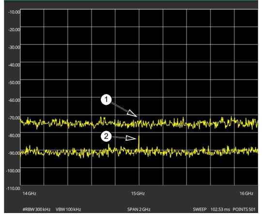
The preamplifier can be turned on and off by toggling PRE AMP via the status panel or the AMPLITUDE menu. Figure: 1. Preamplifier Off 2. Preamplifier On shows the noise floor with the preamplifier off (1) and on (2). Note that when the preamplifier is turned on, the noise floor drops significantly and a low-level signal is exposed. In order to use the preamplifier, the attenuation must be lower than 20 dB. If the preamplifier is turned on when the attenuation is greater than or equal to 20 dB, the attenuation will automatically drop to 10 dB. When AUTO ATTEN is toggled on, the REF LEVEL must be set to –40 dBm or lower to enable the preamplifier.
1. Preamplifier Off 2. Preamplifier On
Indications of Excessive Signal Level
The Field Master Series has built-in features to help prevent input overload. These include auto attenuation and reference level. The instrument will also indicate when a received signal is too high for the current setup by displaying an “ADC Overrange” notification in the title bar (Figure: ADC Overrange). Before proceeding with the measurements, adjust the reference level, the attenuation level, and disable the preamplifier if necessary. Adjusting the resolution bandwidth and frequency range may also help when measuring small signals that are near large signals.
ADC Overrange
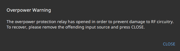
Overpower Warning
The Field Master Series MS2080A/MS2070A and Site Master MS2089A instruments are equipped with an in-built overpower protection hardware in order to manage considerably high range of input power. If the input power range exceeds beyond 5 watts, the protection relay gets activated and a notification alert is displayed as shown in the Figure: Overpower Warning. Proceed by removing the high power input source to avoid to damaging the RF circuitry.