This section describes the Interference Polar capability and key characteristics of Interference Polar measurement mode. This is an alternative technique to geo-locate a potentially interfering signal without having to go to multiple locations. The user stands at a fixed location and makes a full rotation along with the MA2700A handheld InterferenceHunter and a directional antenna through 360º. A polar plot of the signal strength in all directions is displayed on the map.
The polar plot of the interfering signal is located by following the steps below:
1. Select System menu, go to SETTINGS > GPS, and toggle GPS/GNSS on.
2. Select System menu, go to TOOLS > MAP TOOL to download a digital map of the current location. Note that Internet connection is required to download the map tiles of the selected location. Ensure to have either an Ethernet or a Wi-Fi connection.
3. Connect the GPS, MA2700A handheld InterferenceHunter and suitable directional antenna (for e.g. Yagi antenna) to instrument.
5. Set up the frequency and span in order to view the signal of interest on the spectrum display. Ensure not to make the span too wider, as this slows down the instrument’s response in locating the interfering signal.
6. Select SETUP > INTEGRATION BW and set an appropriate integration bandwidth to measure the channel power of the signal of interest.
7. Select SETUP > VOLUME to increase the instrument’s volume in order to listen for max channel power.
8. Select SETUP menu and press START MEAS and slowly make a full rotation in clock-wise direction holding the directional antenna to complete 360º. Refer to SETUP Menu (Interference Polar).
9. Notice that the rotation of the antenna places series of red lines to create a polar plot of the signal in every direction. The direction of maximum signal strength indicates the transmitter that is the source of the interfering signal.
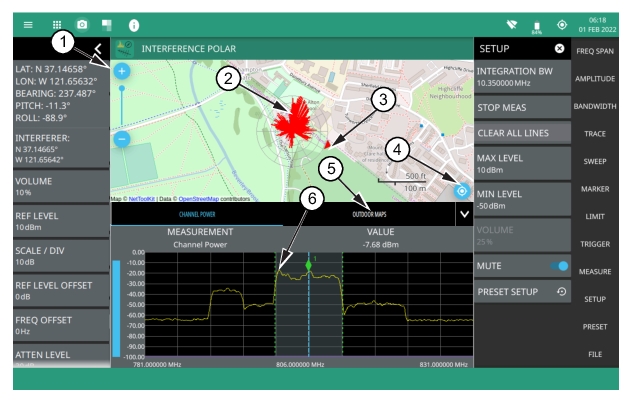
Interference Polar Measurement
1. The map zoom tool is used to increase (+) or decrease (-) zoom level. You can also drag the zoom level indicator up or down, or you can pinch to change zoom level.
2. Interference signal.
3. Direction of bearing degrees.
4. Re-centering tool to center map on current GNSS (GPS) position. A GPS is required for this icon to appear.
5. Select Outdoor Maps to view the list of saved maps or to create a new map using Map tool.
6. Max channel power.
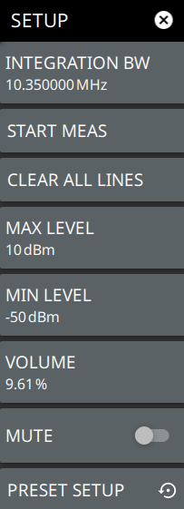
SETUP Menu (Interference Polar)
The Interference Polar SETUP menu is available in MEASURE > MEASUREMENT > Interference Polar > SETUP.
SETUP Menu (Interference Polar)
INTEGRATION BW
Sets the range of integration used in calculating the received power. The integration bandwidth is displayed as the shaded region between the bandwidth start and stop thresholds (dashed green lines).
START MEAS/STOP MEAS
Stay in one location and slowly your turn yourself around holding the antenna in the front to complete a full 360º rotation. This measures a plot of signal strength in every direction, called a polar plot. Select STOP MEAS to stop locating the signal.
CLEAR ALL LINES
Clears all the red lines on the map.
MAX LEVEL
Sets the upper level for the audio response of the measurement. This setting is useful for adjusting the resolution of the tone changes. Power levels above the MAX LEVEL will continue to emit sound an increasingly higher pitch.
MIN LEVEL
Sets the lower level for the audio response of the measurement. The MIN LEVEL also functions as a squelch. Power below this level will not emit a sound.
VOLUME
Sets the audio output volume.
MUTE
Mutes the instrument volume.
PRESET SETUP
Presets all values on the SETUP menu to default values.