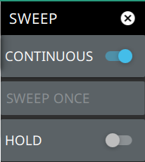
Toggles between continuous sweep and single sweep. In single sweep, the results of a sweep are displayed on the screen while the instrument awaits a trigger event to start a new sweep. The current state of the instrument is displayed in the status panel. With average/hold number (in TRACE menu) set to 1, or averaging is off, or no trace in trace average or hold, a single sweep is equivalent to a single measurement. A single sweep is taken after the trigger condition is met and the analyzer stops sweeping once that sweep has completed. To take one more sweep without resetting the average count, press the SWEEP ONCE button. This sweep control is also available in the status panel.
SWEEP ONCE
When sweep is set to single sweep, SWEEP ONCE triggers a single measurement sweep.
HOLD
Hold will hold the current data display while the analyzer continues to capture and analyze data in the background.
SWEEP Menu – LTE RF Measurements
SWEEP Menu - LTE RF Measurements
CONTINUOUS
Toggles between continuous sweep and single sweep. In single sweep, the results of a sweep are displayed on the screen while the instrument awaits a trigger event to start a new sweep. The current state of the instrument is displayed in the status panel. With average/hold number (in TRACE menu) set to 1, or averaging is off, or no trace in trace average or hold, a single sweep is equivalent to a single measurement. A single sweep is taken after the trigger condition is met and the analyzer stops sweeping once that sweep has completed. To take one more sweep without resetting the average count, press the SWEEP ONCE button. This sweep control is also available in the status panel.
SWEEP ONCE
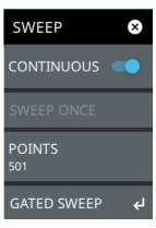
When sweep is set to single sweep, SWEEP ONCE triggers a single measurement sweep.
POINTS
Sets the number of data points per sweep and displayed in each trace. The current value of points is displayed parenthetically, next to the sweep time in the lower-right corner of the display. Using more points provides greater resolution. Using fewer points compacts the data and decreases the time required to access a trace.
Gated sweep is only available on instruments with Option 90 installed and only when an RF-based measurement is selected (Channel Power or Channel Spectrum). Gated sweep allows you to synchronize your sweep with an event so that the analyzer collects data at the appropriate time. This is useful for measuring signals in the time domain such as pulsed RF, time multiplexed, or burst modulated signals. The instrument can use the GNSS (GPS) timing signal as the gating trigger event. This will allow you to synchronize measurements with GNSS (GPS) synchronized communication signals. Set up gated sweep from the GATED SWEEP Menu.
To set up the instrument for gated sweep measurements:
1. Press SWEEP > GATED SWEEP.
2. Select the GATE SOURCE. The gate source selected determines the trigger source from which the gate is controlled. Not all instrument models and options support all triggering selections, so your choices may vary. The instrument supports a GNSS (GPS) and external trigger gate source.
3. Select one of the available FRAME TIME durations. The frame time sets the total measurement cycle time.
4. Set the GATE DELAY time. The gate delay sets the time from the triggering event to when the instrument starts sweeping and collecting data.
5. Set the GATE LENGTH time. The gate length sets the time for data capture and analysis.
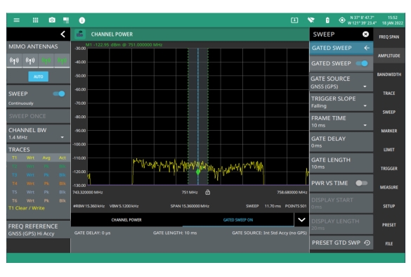
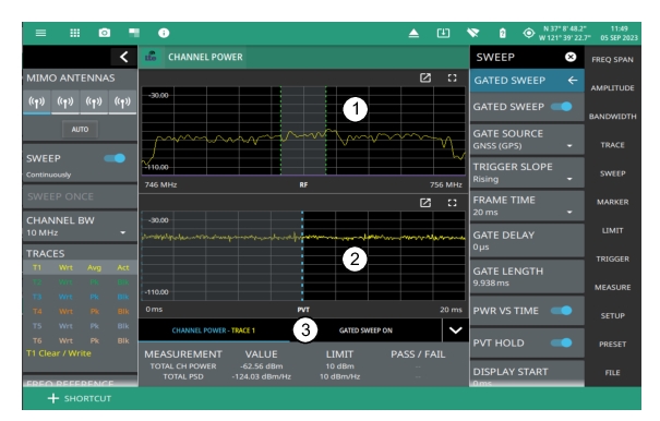
Below is an example of a gated sweep applied to a channel power measurement. The signal level shown varies cyclically with time and would not be measurable without gated sweep.
Gated Sweep Measurement
The channel power and gated sweep display panels at the bottom can be tapped to open either the Channel Power SETUP menu or the GATED SWEEP menu.
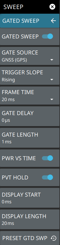
GATED SWEEP Menu
GATED SWEEP Menu
GATED SWEEP
Toggles gated sweep on or off.
GATED SOURCE
Selects the trigger source for the gated sweep.
• GNSS (GPS): This setting synchronizes the trigger source to the GPS PPS.
• External 1 or 2: Sets the gate reference based on input from the External 1 or External 2 port. Only Field Master Pro and Remote Spectrum Monitor instruments have two external ports.
TRIGGER SLOPE
Used when the trigger source is set to External or Video. Sets the trigger slope to rising, falling, or both. When slope is set to Both, the analyzer triggers on both the rising and falling edges. Triggering on both rising and falling edges is not available in zero span.
FRAME TIME
Selects the frame time duration of 10 ms, 20 ms, or 1 s.
GATE DELAY
Sets the start of the gated sweep. When GATED SWEEP ON Display is enabled, the gate delay is indicated by the blue left border of the power vs time display. You can also drag the entire gate to set the desired gate delay.
GATE LENGTH
Sets the length of the gated sweep. When GATED SWEEP ON Display is enabled, the gate length is indicated by the width between the blue borders of the power vs time display. You can also drag the right blue border to set the desired gate length.
When Power vs Time is selected, sets the start of the graticule display.
DISPLAY LENGTH
When Power vs Time is selected, sets the time length of the graticule display.
PRESET GTD SWP
Presets gated sweep settings to default values.
GATED SWEEP ON Display
When gated sweep toggle in turned ON, a time-domain graph is displayed on the bottom and frequency domain graph is shown on top of it, as shown in .Figure: Gated Sweep ON Display
Gated Sweep ON Display
1. Frequency domain graph.
2. Time domain graph.
3. Tabbed table showing the selected measurement and the Gated Sweep details.
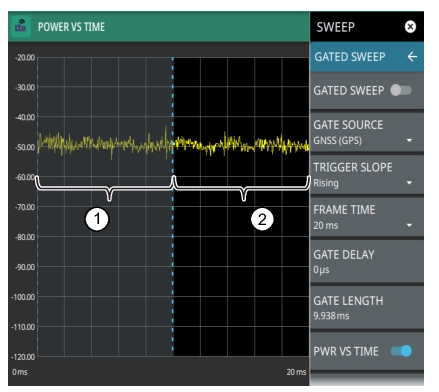
POWER VS. TIME Display
When power vs time is enabled, a time-domain graph is presented. This graph is a useful visual aid when setting up the GATE DELAY (1) and GATE LENGTH (2) times as you can simultaneously view the signal level within the set frame and relative to your gate delay and length. The display is enabled using the PWR VS TIME toggle setting and should be disabled after setting up the gate delay and length parameters. The gate delay and length are represented by the width of the displayed shaded area flanked with blue lines (see Figure: Power vs. Time Display).
Power vs. Time Display
1. Set the gate delay by dragging the left blue setting line. The full time scale is shown along the bottom and the gate delay time will be displayed at the top center of the graticule when it is being adjusted.
2. Set the gate length by dragging the right blue setting line. The full time scale is shown along the bottom and the gate length will be displayed at the top center of the graticule when it is being adjusted.
If the blue gate delay and length setting lines are set outside of the displayed graticule scale, you will see “< Gate Start” and “Gate Stop >” messages at the edge of the display indicating where the blue setting lines are located.
Once the gate has been set up, you can apply gating to the spectrum by toggling GATED SWEEP on. Gating will continue to be applied when you access other measurements and functions of the spectrum analyzer until gated sweep is toggled off or an unsupported instrument configuration is selected.