![]() |
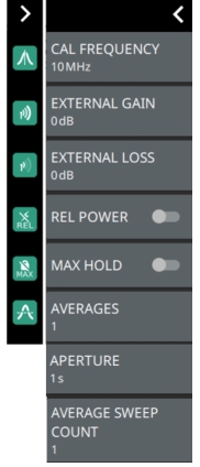
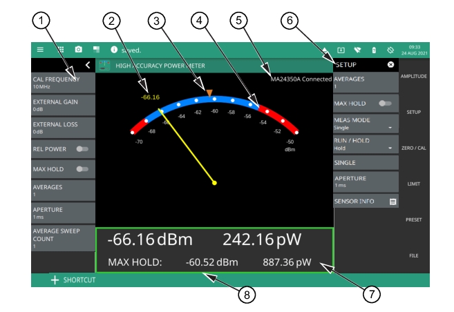
1. Status Panel: This menu provides quick access to common settings used for power meter measurements. Refer to Status Panel. 2. Current Power Measurement: The number displayed here is the current power measurement (in dBm or watts) or the current relative power in dB or percentage. The number here tracks the analog meter pointer. 3. Max Hold Marker: The marker here indicates the max hold value. The max hold value is also displayed in the table below the meter. 4. Limits: The red/blue transitions on the scale indicate the upper and lower limit values. When the pointer is in the blue region, the measurement is passing; when the pointer is in the red regions, the measurement is failing. 5. Sensor Model: The connected sensor model number and status is displayed here. 6. SETUP Menu: Provides access to the main measurement setup parameters. 7. Measurement Table: The data here shows the current and max hold power measurements in both dBm and watts, or relative power in dB and percent (%). 8. Limit Pass/Fail: The measurement table boarder is shown in red for failing measurements or green for passing measurements. |
![]() | CAL FREQUENCY Sets the measurement frequency. The frequency value is sent to the power sensor to apply the appropriate calibration factor. EXTERNAL GAIN Select this submenu key to toggle relative power On or Off. This measurement shows the relative level of the desired base power level input to your instrument. When ON, the message EXTERNAL LOSS Select this submenu key to toggle relative power On or Off. This measurement shows the relative level of the desired base power level input to your instrument. When ON, the message REL POWER Toggles relative power On or Off. This measurement shows the relative level of the desired base power level input to your instrument. For example, if you are measuring a 10 dBm signal, and REL POWER is enabled, then a drop to 7 dBm will show as –3 dB and 50 %. MAX HOLD Max Hold retains the highest power level measurement. AVERAGES Sets the number of measurements to be averaged. APERTURE Aperture is defined as the total time the power sensor observes the input signal in order to complete one power measurement. This tile applies to MA24108/MA24118/MA24126A models only. For MA24106A power sensor models APERTURE MODE is displayed. Refer to SETUP Menu. AVERAGE SWEEP COUNT It is the total number of average sweep count. The value is incremented after every sweep until it becomes equal to the set Averages value. |