Remote programming and operation of the instrument is accomplished via the Ethernet or WLAN (Wi-Fi), or USB C interfaces. The following sections provide information about the interface connections, cable requirements, and remote operation setup.
Network Interface Connection and Setup
The MS2085A/89A uses Ethernet or WLAN to communicate remotely with a controller. Most instrument functions (except power on/off) can be controlled via a network connection to a PC connected directly (with an Ethernet cross‑over cable or Wi-Fi peer-to-peer/ad hoc) or through a network. The instrument software supports the TCP/IP raw socket network protocol.
Ethernet networking uses a bus or star topology in which all of the interfacing devices are connected to a central cable called the bus, or are connected to a hub. Ethernet uses Carrier Sense Multiple Access/Collision Detection (CSMA/CD) access method to handle simultaneous transmissions over the bus. This standard enables network devices to detect simultaneous data channel usage, called a collision, and provides for a contention protocol. When a network device detects a collision, the CSMA/CD standard dictates that the data is retransmitted after waiting a random amount of time. If a second collision is detected, the data is again retransmitted after waiting twice as long. This is known as exponential back off.
Wi-Fi uses a similar star topology in which all of the interfacing devices are connected to an access point. Wi-Fi uses Carrier Sense Multiple Access/Collision Avoidance (CSMA/CA) access method to handle simultaneous transmissions. CSMA/CA doesn’t detect collisions but rather avoids them through the use of a control message. If the control message collides with another control message from another node, it means that the medium is not available for transmission and the back-off algorithm is applied before attempting another transmission.
The TCP/IP setup requires the following:
• IP Address: Every computer and electronic device in a TCP/IP network requires an IP address. An IP address has four numbers (each between 0 and 255) separated by periods. For example: 128.111.122.42 is a valid IP address.
• Subnet Mask: The subnet mask distinguishes the portion of the IP address that is the network ID from the portion that is the station ID. The subnet mask 255.255.0.0, when applied to the IP address given above, would identify the network ID as 128.111 and the station ID as 122.42. All stations in the same local area network should have the same network ID, but different station IDs.
• Default Gateway: A TCP/IP network can have a gateway to communicate beyond the LAN identified by the network ID. A gateway is a computer or electronic device that is connected to two different networks and can move TCP/IP data from one network to the other. A single LAN that is not connected to another LAN requires a default gateway setting of 0.0.0.0. If you have a gateway, then the default gateway would be set to the appropriate value of your gateway.
• Ethernet Address: An Ethernet address, or Media Access Control (MAC) address, is a unique 48‑bit value that identifies a network interface card to the rest of the network. Every network card has a unique Ethernet address permanently stored into its memory.
• Remote programming and operation between the instrument and remote program is accomplished via a TCP/IP raw socket connection to port 9001. The remote program must establish a TCP/IP raw socket connection at port 9001 to the MS2085A/89A.
• The remote application may connect to the instrument IP address or to its HOSTNAME. If using DHCP instead of a static IP, using the HOSTNAME may be more reliable for finding an instrument on a network.
• You may need to contact your network administrator to ensure network security policies, antivirus, and firewall settings do not block access to the controlling computer and its ports.
The MS208xA can be configured for Dynamic Host Configuration Protocol (DHCP), an Internet protocol that automates the process of setting IP addresses for devices that use TCP/IP, and is the most common method of configuring a device for network use.
To determine if a network is set up for DHCP, connect the instrument to the network and select DHCP protocol. Power cycle the instrument. If the network is set up for DHCP, the assigned IP address should be displayed in the network settings.
Network Connection
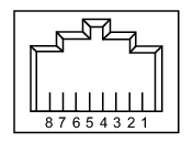
Interface between the instrument and other devices on the network is via a category five (CAT‑5) interface cable connected to a network. This cable uses four twisted pairs of insulated copper wires terminated into an RJ45 connector. CAT‑5 cabling is capable of supporting frequencies up to 100 MHz and data transfer speeds up to 1 Gbps, which accommodates 1000Base‑T, 100Base‑T, and 10Base‑T networks. CAT‑5 cables are based on the EIA/TIA 568 Commercial Building Telecommunications Wiring Standard developed by the Electronics Industries Association. A pinout diagram is shown in Table: 8‑pin Ethernet RJ45 Connector Pinout Diagram.
8‑pin Ethernet RJ45 Connector Pinout Diagram
Pin
Name
Description
Wire Color
1
TX+
Transmit data (> +3 volts)
White/Orange
2
TX–
Transmit data (< –3 volts)
Orange
3
RX+
Receive data (> +3 volts)
White/Green
4
–
Not used (common mode termination)
Blue
5
–
Not used (common mode termination)
White/Blue
6
RX–
Receive data (< –3 volts)
Green
7
–
Not used (common mode termination)
White/Brown
8
–
Not used (common mode termination)
Brown
Integrated into the RJ45 connector are two LEDs. The amber LED indicates the presence of LAN voltages (a live LAN connection) while the green LED flashes to show that LAN traffic is present. The instrument IP address and its HOSTNAME are set via the System menu (upper left corner) and accessing the Ethernet or WIFI settings menu.
TCP/IP connectivity requires setting up the parameters described at the beginning of this section. The following is a brief overview of how to set up a general LAN connection on the MS2085A/89A.
Note
You may need to consult your network documentation or network administrator for assistance in configuring your network setup.
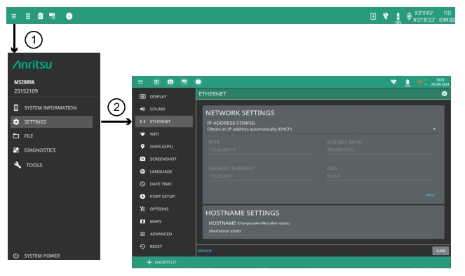
1. Access the System menu (three line icon in upper left corner).
2. Press SETTINGS to access the instrument settings menu, then select either Ethernet or WIFI to change the IP address or HOSTNAME.
Network Settings
When using Ethernet, the instrument IP address can be set automatically using DHCP or manually by entering the desired IP address, gateway address, and subnet mask. DHCP is an Internet protocol that automates the process of setting IP addresses for devices that use TCP/IP, and is the most common method of configuring a device for network use.
To determine if a network is set up for DHCP, connect the instrument to the network and select DHCP protocol. Power cycle the instrument. If the network is set up for DHCP, the assigned IP address should be displayed in the network settings.
Note
An active Ethernet cable must be connected to the instrument before it is turned on in order to enable the Ethernet port for DHCP or for a static IP address. Depending on local conditions, the port may remain enabled when changing between DHCP and static IP address, or when temporarily disconnecting the Ethernet cable. If the port becomes disabled, verify that an active Ethernet cable is attached to the instrument, then cycle the instrument power off and on
When using Wi-Fi, an active Wi-Fi connection to an access point that is connected to your network must be established in order to enable DHCP. Static IP and HOSTNAME connections are not supported by the MS2085A/89A.