The MS2085A/89A status system consists of the following SCPI-defined status-reporting structures:
• The Instrument Summary Status Byte Group
• The Standard Event Status Group
• The Operation Status Group
• The Questionable Status Group
The following paragraphs describe the registers that make up a status group and explain the status information that each status group provides.
Note
Parallel Polling is not supported in the MS2085A/89A.
Status Group Registers
In general, a status group consists of a condition register, a transition filter, an event register, and an enable register. Each component is briefly described in the following paragraphs.
Condition Register
The condition register is continuously updated to reflect the current status of the MS2085A/89A. There is no latching or buffering for this register, it is updated in real time. Reading the contents of a condition register does not change its contents.
Event Register
The event register latches transition events from the condition register as specified by the transition filter. Bits in the event register are latched, and once set they remain set until cleared by a query or a *CLS command Event registers are read only.
Enable Register
The enable register specifies the bits in the event register that can produce a summary bit. The MS2085A/89A logically ANDs corresponding bits in the event and enable registers, and ORs all the resulting bits to obtain a summary bit. Summary bits are recorded in the Summary Status Byte. Enable registers are read-write. Querying an enable register does not affect it.
Status Group Reporting
The state of certain MS2085A/89A hardware and operational events and conditions can be determined by programming the status system. Three lower status groups provide status information to the Summary Status Byte group. The Summary Status Byte group is used to determine the general nature of an event or condition and the other status groups are used to determine the specific nature of the event or condition. The following paragraphs explain the information that is provided by each status group. Programming commands for the status system can be found in Common Commands.
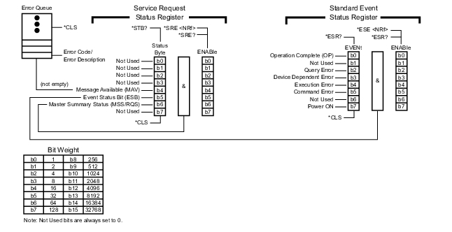
Summary Status Byte Group
The Summary Status Byte group, consisting of the Summary Status Byte Enable register and the Summary Status Byte, is used to determine the general nature of a MS2085A/89A event or condition. The bits in the Summary Status Byte provide the following:
Status Byte Group
Bit #
Bit Name
Description
0,1
Not Used
These bits are always set to 0.
2
Not Used
These bits are always set to 0.
3
Not Used
These bits are always set to 0.
4
Message Available (MAV)
Set to indicate that the MS2085A/89A has data ready in its error queue.
5
Standard Event (ESB)
Set to indicate that the Standard Event Status summary bit has been set. The Standard Event Status register can then be read to determine the specific event that caused the bit to be set.
6
Master Summary Status (MSS/RQS)
Set to indicate that the MS2085A/89A has at least one reason to require service. This bit is also called the Master Summary Status Bit (MSS). The individual bits in the Status Byte are ANDed with their corresponding Service Request Enable Register bits, then each bit value is ORed and input to this bit.
7
Not Used
These bits are always set to 0.
Standard Event Status Group
The Standard Event Status group, consisting of the Standard Event Status register (an Event register) and the Standard Event Status Enable register, is used to determine the specific event that set bit 5 of the Summary Status Byte. The bits in the Standard Event Status register provide the following:
Standard Event Status Group
Bit #
Bit Name
Description
0
Operation Complete (OP)
Set to indicate that all pending MS2085A/89A operations were completed following execution of the “*OPC” command.
For more information, see the descriptions of the *OPC, *OPC?, and *WAI commands in Common Commands.
1
Not Used
The bit is always set to 0.
2
Query Error
Set to indicate that a query error has occurred (error -400 in SCPI Error Table).
3
Device Dependent Error
Set to indicate that a device-dependent error has occurred (errors -300 to -399 in SCPI Error Table).
4
Execution Error
Set to indicate that an execution error has occurred (errors -200 to -299 in SCPI Error Table).
5
Command Error
Set to indicate that a command error (usually a syntax error) has occurred (errors -100 to -199 in SCPI Error Table).
6
Not Used
This bit should be set to 0 (zero).
7
Power ON
Set to indicate that the MS2085A/89A is powered ON and in operation.
Operation Status Group
The Operation Status group, consisting of the Operation Condition register, the Operation Positive Transition register, the Operation Negative Transition register, the Operation Event register, and the Operation Event Enable register, is used to determine the specific condition that set bit 7 in the Summary Status Byte. The bits in the Operation Event register provide the following:
Operation Status Group
Bit #
Bit Name
Description
0-7
Not Used
This bit should be set to 0 (zero).
8
Sweep Complete
Set to indicate that a sweep is complete.
9
I/Q Capture
Set to indicate that I/Q data capture is in process.