This section illustrates the main graphical displays presented for the cable and antenna analyzer of Field Master and Site Master series instruments. For an introduction to cable and antenna measurements, refer to Measurement Overview. For a general overview of the instrument and its user interface, refer to Instrument Overview chapter of the product user guide.
Note
The instrument software user interface for Field Master and Site Master instruments is almost the same except with a few differences in the calibration menu, status panel and sweep menu.
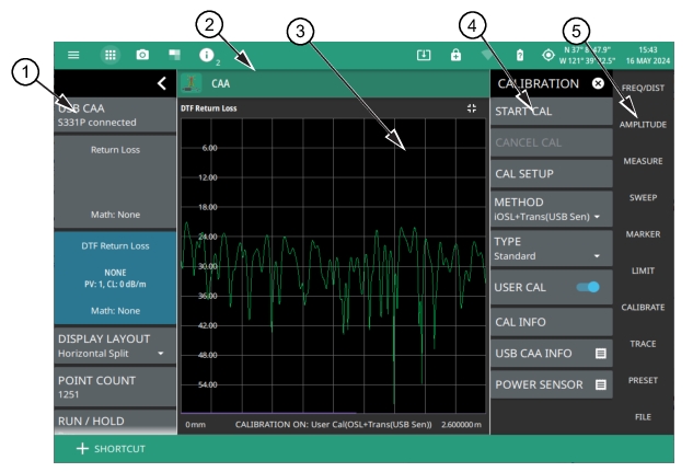
Field Master Series Cable Antenna Analyzer GUI Overview
1. Status Panel: The cable and antenna analyzer status panel displays general settings for the current measurement. Refer to Status Panel.
2. Title Bar: The title bar provides quick access to system settings, measurement mode selection, informational dialogs, and screen capture. Refer to Selecting the Analyzer - Field Master.
3. Main Measurement Display: This area shows active measurement either in single or dual display. Refer to Display Layout.
4. Calibration Menu: Access all the calibration settings and methods from here. Refer to CALIBRATION Menu.
5. Main Menu: Access all setup and measurement configuration menus from here. Refer to Main Menu.
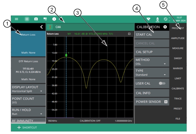
Site Master Cable Antenna Analyzer GUI Overview
1. Status Panel: The cable and antenna analyzer status panel displays general settings for the current measurement. Refer to Status Panel.
2. Title Bar: The title bar provides quick access to system settings, measurement mode selection, informational dialogs, and screen capture. Refer to Selecting the Analyzer - Site Master.
3. Main Measurement Display: This area shows trace data and the marker table. Refer to Display Layout.
4. Calibration Menu: Access all the calibration settings and methods from here. Refer to CALIBRATION Menu.
5. Main Menu: Access all setup and measurement configuration menus from here. Refer to Main Menu.
Display Layout
The Cable and Antenna Analyzer CAA can display a single measurement or two different measurements simultaneously (Horizontal Split). Different amplitudes, limit lines, and markers can be set for each display; the frequency range and calibration parameters are common to both displays. Marker and limit line tables can be toggled on and off, showing all marker and limit line values for either the single measurement or both measurements. Figure: Single Measurement Display (Field Master Series) shows an overview of the measurement display area for a single measurement display layout.
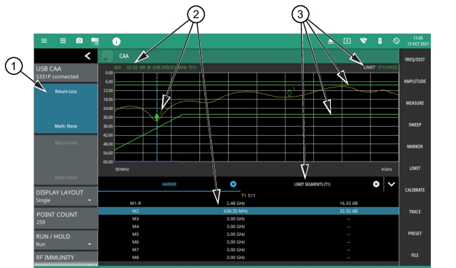
Single Measurement Display (Field Master Series)
1. Trace Card: In single display layout, the upper trace card identifies the measurement type and related details. See Status Panel for a description of trace cards.
2. Markers: Marker data is displayed at the top of the measurement scale and in the marker table below the measurement. The active marker has a solid fill and is highlighted in the marker table. The vertical blue line is also placed on the active marker and can be used to drag the markers position. Refer to Setting Up Markers.
3. Limits: When enabled, limit lines appear on the display as green (passing) or red (failing). The pass/fail condition is indicated at the top of the scale. Additionally, when segmented limit lines are enabled, a limit table can be toggled on. Refer to Setting Up Limit Lines.
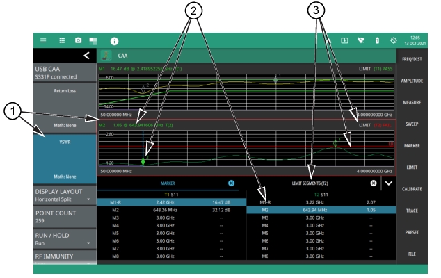
1. Trace Card and Active Trace: In horizontal split (dual) display layout, the active trace card is highlighted in blue and identifies the measurement type and related details. In addition, the active trace measurement area is outlined in a red box. See Status Panel for a description of trace cards. The settings for amplitude, measurements, markers and limits, and trace memory apply only to the active trace measurement.
2. Markers: Marker data is displayed at the top of the measurement scale and in the marker table below the measurements. The active marker has a solid fill and is highlighted in the marker table. The vertical blue line is also placed on the active marker and can be used to drag the marker position. The marker table applies to the active trace measurement only. Refer to Setting Up Markers.
3. Limits: When enabled, limit lines appear on the display as green (passing) or red (failing). The pass/fail condition is indicated at the top of the scale. Additionally, when segmented limit lines are enabled, a limit table can be toggled on. The limit table applies to the active trace measurement only. Refer to Setting Up Markers.
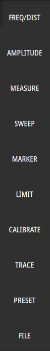
Main Menu
The main menu is the primary access point for all instrument controls and measurement selections. The main function for each main menu button is described below.
Main Menu
-
FREQ/DIST
Contains all frequency and distance settings including start and stop frequency, measurement distance, distance-to-fault (DTF), and cable parameters. Refer to Setting Frequency and Distance Parameters.
AMPLITUDE
Provides access to all amplitude-related settings such as top and bottom of the graticule and scale settings. Refer to Setting Amplitude Parameters.
MEASURE
Used to select the measurement trace and measurement type such as return loss, VSWR, DTF, cable loss, smith chart, and one-port phase, and for setting the display layout. Refer to Setting up a Measurement.
SWEEP
Provides controls for sweep behaviors, number of measurement points, and RF immunity settings. Refer to Setting Sweep Parameters.
MARKER
Used to enable and set all marker-related parameters and provides access to the marker table. Refer to Setting Up Markers.
LIMIT
Provides controls for setting up limit lines and limit alarms. Refer to Setting Up Limit Lines.
CALIBRATE
Sets the calibration type and method and begins the calibration. Refer to CALIBRATION Menu.
Opens the PRESET menu with selective trace, marker, and setup preset commands, or an all inclusive analyzer preset command. Refer to Presetting the Analyzer.
FILE
Used to save and recall instrument setups and measurements, and screen images. Also provides access to save on event controls. Refer to FILE Menu and the “File Management” section in the Instrument overview chapter of the user guide.
Using Menus
Instrument setup, control, and measurement functions are performed through the use of menus. Menu behaviors are summarized below:
• Selecting a main menu button opens the associated menu.
• The name of the button selected in the main menu is reflected in the title bar of the resulting menu.
• Menu buttons can change for various measurement settings, instrument setup parameters, and measurement views.
• Selecting the corresponding main menu button for a menu closes the menu.
• Touching status data, a parameter field, or label in the display area opens the corresponding menu and the associated keypad for editing that parameter setting.
• Selecting Accept, Cancel, or the X in the upper right corner closes the menu or keypad.
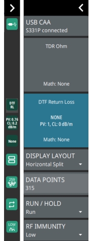
Status Panel
The status panel with the corresponding minimized status panel icons illustrated in this section are unique to the CAAUSB and to the particular measurement and view that is selected. Below is the CAAUSB status panel that covers all cable and antenna analyzer measurements, including return loss, voltage standing wave ratio, distance-to-fault, smith chart, and 1-port phase, and transmission measurements (selected via MEASURE > MEASUREMENT menu).
Note
The MS2085A/89A instrument status panel does not include “USB CAA S331P connected” tile, as it does not require an external S331P instrument to make cable and antenna measurements.
Cable and Antenna Analyzer Status Panel with Mini Status Panel Icons (Field Master Series)
Selecting any of these parameters opens the associated menu or quick access pop-up that allows you to conveniently change the parameter value. These are the same settings found in the right side menus.
USB CAA
Indicates the model of the connected sensor. Only included in Field Master instruments.
Top and Bottom Trace Cards
Each trace card is divided into three separate sections that display information relevant to the selected measurement:
• The top area displays the selected measurement.
• When the measurement type is DTF or cable loss, the middle area displays cable information (cable list selection, propagation velocity, and/or cable loss information). When the measurement type is transmission, it displays the connected sensor information.
• The bottom area displays the trace math setting. Each of these areas are touchable and will access the relevant settings.
DISPLAY LAYOUT
Selects between a single, full-size measurement layout or horizontal split layout.
DATA POINTS
Sets the number of display points currently measured by the instrument. Note that increasing the number of display points can improve the resolution of measurements in addition to increase in sweep time. Refer to DATA POINTS.
RUN/HOLD
Sets the sweep to either run or hold mode. Refer to RUN/HOLD.
RF IMMUNITY
Sets the reflection RF measurement to High or Low. Refer to RF Immunity.