To select transmission measurement go to main menu and press MEASURE > MEASUREMENT >Transmission. Transmission measurement is only available if tracking generator Option 20 is installed. Transmission measurement includes a tracking generator that generates a swept signal with an output frequency that is the same as the tuning frequency of the spectrum analyzer, and a continuous wave (CW) generator that allows the user to set sine wave output frequency and power. Power output information is available for both absolute and transmission (normalized) measurements.
Note
The Transmission measurement is only available when Tracking Generator Option 20 is installed. The Option 20 is only offered in MS2085A/89A Site Master and MS2080A Field Master instruments.
Transmission Measurement
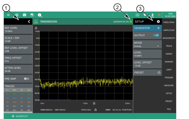
1. The status panel provides quick access to common spectrum analyzer settings. See STATUS PANEL (Transmission).
2. The GENERATOR ON appears on the top right, when the OUTPUT toggle is turned on. The green light indicates that the tracking generator or CW generator is on.
3. The setup menu is used to set transmission measurement parameters. See SETUP Menu (Transmission). Note that touching GENERATOR ON indicator will bring up the GENERATOR submenu. Refer to GENERATOR Menu (Option 20) for details.
STATUS PANEL (Transmission)
Below is the status panel with the corresponding minimized status panel icons for Transmission measurement.
Status Panel with Minimized Status Panel Icons (Transmission)
REF LEVEL
Sets the reference level of the top graticule line in the selected units. If the reference level offset is not zero, OFFSET REF LEVEL is displayed at this location. Refer to Setting Amplitude Parameters.
SECOND REF LEVEL
The reference level is the top graticule line to the right on the measurement display. Its functionality is exactly same as reference level, but it is only available when trace math is enabled.
SCALE/DIV
Sets the graticule scale/division for log-based units. This setting does not apply to linear units.
SECOND SCALE/DIV
It applies to second reference level and is available only when trace math is enabled.
REF LEVEL OFFSET
Sets the reference level offset in dB units. This setting can compensate for the presence of external input attenuation or gain.
Displays the current status of up to six traces in a quick-view summary.
The summary information includes the trace number, type, mode, and detector type. The active trace is shown with a highlighted background including the mode and detector type restated under the table. The reference trace settings are applied to all traces. Selecting a trace in the summary panel activates the pressed trace and opens the TRACE menu, allowing you to select and set up an individual trace as desired. Refer to Setting Trace Parameters.
TRACE STATS (dBm)
Displays the spectrum analyzer received maximum, average, and minimum power of each frequency range sweep.
SWEEP
Toggles the current sweep setting between continuously or sweep once. Refer to Setting Sweep Parameters.
FREQ REFERENCE
Indicates the current frequency reference source of Internal High Accuracy (used after GPS has lost sync, but while the internal clock still has good GPS reference), Internal Standard Accuracy, External, or GNSS (GPS) Hi Accuracy (requires GPS). The instrument automatically selects the frequency reference in the following order of priority: external, GPS, then the internal time base.
SETUP Menu (Transmission)
To access the SETUP menu select MEASURE > MEASUREMENT > Transmission > SETUP, or press SETUP menu from the main menu. The setup menu consists of GENERATOR submenu.
Go to main menu select MEASURE > MEASUREMENT > Transmission >GENERATOR. The Generator submenu is only available on instruments installed with Tracking Generator (Option 20). The transmission measurement supports 4 different generator modes. Set the instrument to Sweep or Offset Sweep modes to make tracking generator measurements. Set your instrument to CW fixed or CW Coupled modes to make CW generator measurements. The output power is leveled and has a specified power range –50 dBm to +0 dBm in 1 dB steps.
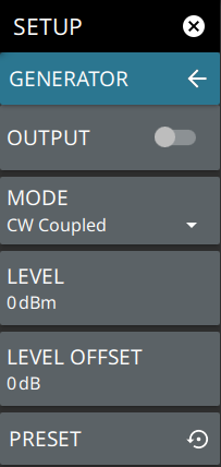
GENERATOR Submenu
OUTPUT
Slide the toggle to turn the generator on/off. Source output power level can be set using LEVEL.
MODE
Selects one the following generator modes:
• Sweep: Generates a swept signal with an output frequency equal to the tuning frequency of the spectrum analyzer.
• Offset Sweep: Generates a swept signal with an output frequency modified by a selected offset, relative to the tuning frequency of the spectrum analyzer.
• CW Fixed: Generates a continuous wave (CW) signal with a fixed output frequency.
• CW Coupled: Generates a CW signal with an output frequency equal to the center frequency of the spectrum analyzer.
LEVEL
Sets the source output power level (in dBm). It corresponds to actual output power setting regardless of any external gain or loss setting.
LEVEL OFFSET
Sets the source output offset value or external gain/loss (in dB).Note that changing this value adjusts the displayed output power in accordance with the set offset. For example, if the output power is set to –25 dBm, and if the external gain/loss is then set to 10 dB external gain, then the power limits will be adjusted by 10 dB, and the value of the output power that is displayed on the instrument will be adjusted to –15 dBm. The range is from –100 dB to +100 dB. A negative offset indicates an external loss, and a positive value indicates an external gain.
CW FIXED FREQ
Sets source output frequency when the generator mode is set to CW Fixed.
PRESET
Presets all the set parameters to default values.
Tracking Generator Overview
Note
Turning the Tracking Generator on sets the sweep mode to No FFT. Turning off the generator presets the parameters to their previous settings. Either parameter may be changed by the user with the Tracking Generator on or by the instrument when other measurements are also turned on.
Bandpass Filter Testing
The following procedure describes the typical process for testing a bandpass filter:
1. From FREQ/SPAN menu set the frequency range to cover the range of the DUT being tested. In this example, the center frequency is set to 3 GHz (bandpass filter) with a full span of 6 GHz.
2. Select MEASURE > MEASUREMENT > Transmission.
3. Select MEASURE > GENERATOR, or SETUP >GENERATOR and set the parameters as follows:
• OUTPUT: Slide the toggle to turn on the tracking generator
• MODE: Sweep
• LEVEL: 0 dBm
4. Connect the output of the tracking generator to the input of the spectrum analyzer using the RF cables that will be included in the filter measurement. A barrel connector should be used in place of the filter under test.
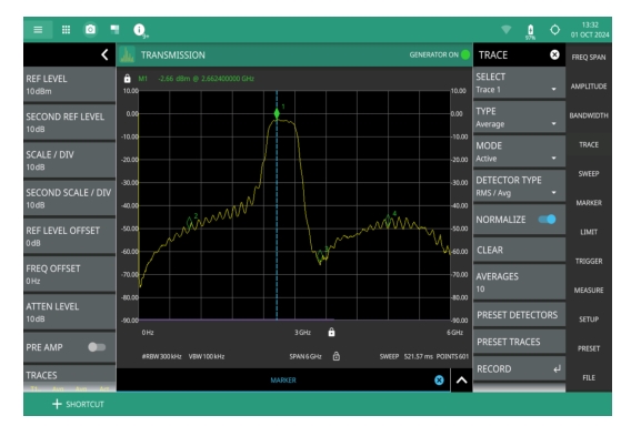
5. Press TRACE menu and turn on the NORMALIZE toggle. This will normalize out the frequency loss of the test cables and display a trace at 0 dB on the instrument.
6. Remove the barrel connector from the test cables and insert the filter under test in its place. Figure: Connection of Bandpass Filter as DUT - Transmission Measurement displays a typical bandpass filter response. For connector Torque and connector care information, refer to the user guide for your instrument.
7. If the spectrum analyzer noise floor is too high for the necessary measurements, then reduce the input attenuation and RBW to maximize the dynamic range. Figure 3-60 shows the sample setup with the input attenuation lowered from 30 dB to 10 dB and with the RBW reduced from 3 MHz to 300 kHz.
8. When measuring a filter with a very high insertion loss in the stop band, press SWEEP menu and increase the number of data points. Increasing the trace point count provides higher resolution for measurements which include rapidly changing frequency response. Typically, setting the point count to 1,001 can measure the high dynamic range of certain filters.
9. From GENERATOR menu slide the OUTPUT toggle to turn on the tracking generator.
Note
If the noise floor drops below the visible display, then set the Scale dB/division setting to a value larger than 10. This will increase the displayed amplitude range.
Connection of Bandpass Filter as DUT - Transmission Measurement
Mixer Testing
In this example the input to the mixer Local Oscillator (LO) is 200 MHz and the RF input range is 4.8 GHz to 5.8 GHz. This generates an Intermediate Frequency (IF) mixer output from 5 GHz to 6 GHz (upper sideband) and 4.6 GHz to 5.6 GHz (lower sideband).
The following procedure describes the typical process for testing a mixer:
1. From FREQ/SPAN menu set the frequency range to cover the range of the DUT being tested. In this example, the frequency range is set to 5 GHz to 6 GHz to view the conversion loss in the upper sideband.
2. Press MEASURE > MEASUREMENT > Transmission.
3. Press MEASURE > GENERATOR, or SETUP >GENERATOR and set the parameters as follows:
• OUTPUT: Slide the toggle to turn on the tracking generator
• MODE: Offset Sweep
• LEVEL: 0 dBm
• FREQ OFFSET: 200 MHz
• LEVEL OFFSET: X dB (enter the value of loss in the test port cables if this is known)
4. Connect a signal generator set to 200 MHz to the mixer LO input. Connect the output of the tracking generator to the mixer RF input and the IF output of the mixer to the spectrum analyzer input. Figure: Connection of Mixer as DUT - Transmission Measurement displays a mixer conversion loss response.
5. To view the conversion loss of the other mixer sideband, change the offset frequency from – 200 MHz to 200 MHz.
Connection of Mixer as DUT - Transmission Measurement
CW Generator Overview
The Tracking Generator Option 20 also includes a continuous wave (CW) generator. The CW Signal Generator provides a continuous wave signal from the GENERATOR/RF OUT port of the instrument. The CW generator consists of two modes CW Fixed and CW Coupled.
CW Fixed/CW Coupled Mode
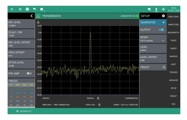
The following example displays the generator CW signal on the instrument display:
1. Connect a THROUGH cable between the RF OUT and RF In connectors of your instrument.
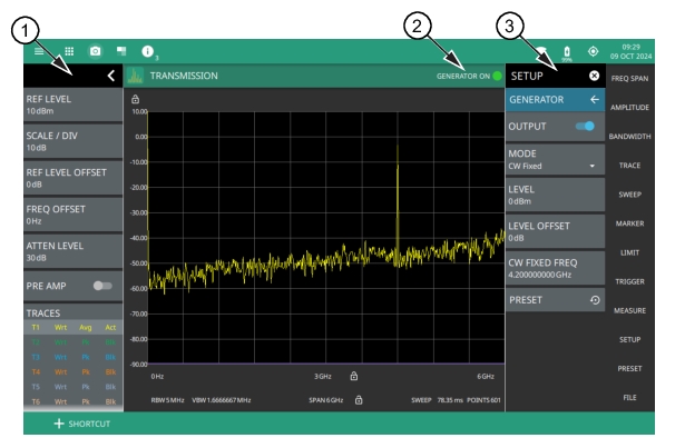
Through Cable Setup Example - Transmission Measurement (CW Fixed Mode)
1. The status panel provides quick access to common spectrum analyzer settings. See STATUS PANEL (Transmission).
2. The GENERATOR ON indicator appears on the top right, when the OUTPUT toggle is turned on. The green light indicates that the generator is on. Touch the indicator to open the GENERATOR submenu. Refer to GENERATOR Menu (Option 20) for details.
3. The setup menu is used to set transmission measurement parameters. See SETUP Menu (Transmission).
2. Set the spectrum analyzer frequency range using the FREQ/SPAN menu and submenus. Refer to the Spectrum Analyzer Measurement Guide (10580‑00447) for additional information.
3. Select the measurement from MEASURE > MEASUREMENT > Transmission.
4. Access GENERATOR submenu from MEASURE > SETUP menu.
5. Turn on the OUTPUT toggle.
6. Set the generator mode to CW Fixed from MODE submenu.
Confirm that the CW Frequency is set within the spectrum analyzer span, or the signal will not be displayed on the instrument.
Through Cable Setup Example - Transmission Measurement (CW Coupled Mode)
1. The status panel provides quick access to common spectrum analyzer settings. See STATUS PANEL (Transmission).
2. The GENERATOR ON indicator appears on the top right, when the OUTPUT toggle is turned on. The green light indicates that the generator is on. Touch the indicator to open the GENERATOR submenu. Refer to GENERATOR Menu (Option 20) for details.
3. The setup menu is used to set transmission measurement parameters. See SETUP Menu (Transmission).