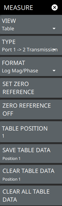
To access the MEASURE menu go to main menu in the vector voltmeter (VVM) application. The MEASURE menu described below is unique to TABLE view.
MEASURE Menu
VIEW
Sets the measurement view to either Single or Table.
TYPE
Selects any one of the measurement types:
• Port 1–>2 Transmission: Select this measurement to make transmission measurements using Port 1.
• Port 1 Reflection/Electrical Length: Select this measurement to make reflection measurements using Port 1.
• A/B Receiver Ratio: Select this measurement determine the ratio of the magnitudes of signal A over signal B and the phase difference between the two signals.
• B/A Receiver Ratio: Select this measurement determine the ratio of the magnitudes of signal B over signal A and the phase difference between the two signals.
• A: Select this measurement while measuring only signal A.
• B: Select this measurement while measuring only signal B.
FORMAT
Selects any of the following measurement formats:
• Log Mag/Phase: Displays the measurement results as logarithmic amplitude in dB on the top and as phase in degrees in the bottom.
• Lin Mag/Phase: Displays the measurement results as linear amplitude in dB on the top and as phase in degrees in the bottom.
• VSWR: Displays the ratio of maximum voltage to the minimum voltage. Not supported when TYPE is set to either Port 1-->2 Transmission, A/B Receiver Ratio, A and B.
• Impedance: Displays the real impedance on the top and imaginary impedance in the bottom. Not supported when TYPE is set to either Port 1-->2 Transmission, A/B Receiver Ratio, A and B.
SET ZERO REFERENCE
Turns on ZERO REFERENCE. Sets the zero reference data for the current measurement type.
ZERO REFERENCE OFF
Turns off the ZERO REFERENCE. Clears the zero reference data for the current measurement.
TABLE POSITION
Sets the active table row position using the numeric keypad. A maximum of 100 rows can be added.
SAVE TABLE DATA
Saves the absolute and relative values of the amplitude and phase.
CLEAR TABLE DATA
Clears the table data for the selected measurement type.
CLEAR ALL TABLE DATA
Clears the entire table data (all rows) of the selected measurement type.
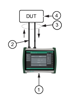
Port 1 Reflection measurement
This technique measures the S11 reflected signal on a component or cable, and depends upon the procedure in which the far end of the cable is deliberately mismatched, either shorted or left open-circuited. This reflects virtually 100% of the input signal, and the phase delay of the measured reflected signal is therefore equal to twice the one-way phase of the cable. Likewise, the cable attenuation is twice the one-way loss. This technique is especially useful for situations in which you must manually create multiple phase matched cables. This would be done by carefully snipping small amounts of cable with a diagonal cutters, perhaps 3 mm at a time, and re-measuring the effect on the 2-way phase. This technique is most often used for cable trimming, but it can also be used to validate the proper electrical length of any low loss DUT. It is most often used with a reference measurement (golden DUT) which is stored into memory, then subsequent DUTs may be measured and compared against the stored reference. As an option, the measurement port may be vector error corrected (via the calibration process) to provide optimal results. This is the simplest and most convenient VVM measurement. Best results are obtained when the DUT loss is < 20 dB. For a very lossy DUT, use the Transmission Measurement type.
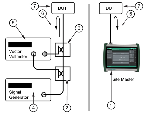
Figure: Vector Voltmeter Reflection Measurement shows a block diagram comparison of the test configuration for the Vector Voltmeter instrument method (left) and the and the equivalent measurement capability integrated within the Site Master in VVM mode right) when the MS208xA is used for S11 reflection measurement. The Vector Voltmeter (when equipped with Option 15) contains not only the Vector Voltmeter receiver, but also the signal source and couplers that are necessary for conducting both 1‑port measurements at a selected CW frequency.
Vector Voltmeter Reflection Measurement
1. MS2085A/89A Site Master
2. Coupler or Splitter
3. Coupler or Bridge
4. Signal Generator
5. Vector Voltmeter
6. Reflection Measurement
7. DUT (Device Under Test)
While phase sensitive cabling is used primarily in lower frequency applications that are typical in air navigation systems such as VOR (VHF Omnirange), the Option 15 software VVM procedures are applicable for the entire frequency coverage of the Vector Voltmeter.
Port 1 Reflection
Refers to the reflection S-parameter (S11) measured at Port 1 of the Vector Voltmeter. It quantifies how much of an incident signal is reflected back due to impedance mismatch at the port.
S11 can be defined as:
where ZLis the load impedance and Z0 is the characteristic impedance of the system (usually 50Ω)
Electrical Length
It is the length of a transmission line or cable measured in terms of the signal wavelength at a specific frequency. It accounts for the phase shift introduced by the length of the line.
The electrical length can be expressed in degrees and is calculated as:
where d is the physical length of the line and λ is the wavelength of the signal.
Port 1–>2 Transmission Measurement
This technique uses the VVM function in a straightforward manner with its 2‑port setup. The transmission response of the DUT is measured from port 1 to port 2. The DUT amplitude and phase shift are measured by the highly sensitive port 2 receiver. The high dynamic range of this measurement is ideal when the DUT loss is high.
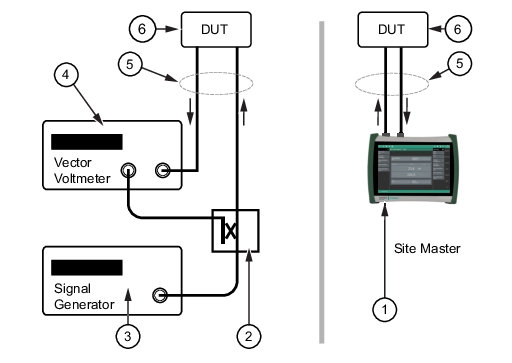
Figure: Vector Voltmeter Port 1–>2 Transmission Measurement shows a block diagram comparison of the test configuration for the Vector Voltmeter instrument method (left) and the equivalent measurement capability integrated within the Site Master in VVM mode (right) when the MS2085A/89A is used for a transmission measurement.
Vector Voltmeter Port 1–>2 Transmission Measurement
(Left) Vector Voltmeter and (Right) MS2085A/89A Site Master Equivalent Measurement
1. MS2085A/89A Site Master
2. Coupler or Splitter
3. Signal Generator
4. Vector Voltmeter
5. Transmission Measurement
6. DUT (Device Under Test)
Transmission S-Parameter
The S21 quantifies how much of the incident signal at Port 1 is transmitted to Port 2. S21 is defined as:
Where Vin is the voltage at Port 1 and Vout is the voltage at Port 2.
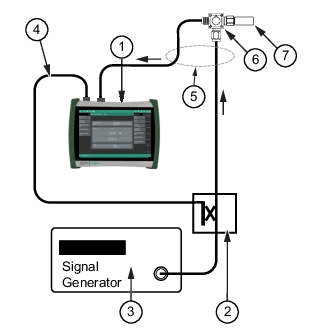
A/B or B/A Measurements
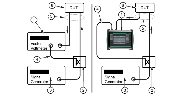
For Reflection or Transmission measurements, the MS2085A/89A VVM function can replace the entire setup of source, VVM, and couplers, as shown in Figure: Vector Voltmeter Reflection Measurement and Figure: Vector Voltmeter Port 1–>2 Transmission Measurement. If the measurement setup still requires the use of an external source and couplers, however, then the MS2085A/89A VVM function can replace only the original Vector Voltmeter by using the A/B or B/A measurement selection. The B/A setup is shown in Figure: Vector Voltmeter B/A Measurement with External CW Source with the traditional Vector Voltmeter instrument method (left) and the equivalent measurement using the Site Master in VVM mode (right). For these measurements, the reference signal is received on one port of the MS2085A/89A (Port 1 for B/A and Port 2 for A/B) while the signal transmitted through or reflected from the DUT is received on the other port.
B/A Measurement
Vector Voltmeter B/A Measurement with External CW Source
(Left) Vector Voltmeter and (Right) MS2085A/89A Site Master Equivalent Measurement
1. Vector Voltmeter or MS2085A/89A Site Master
2. Coupler or Splitter
3. Signal Generator
4. Reference Signal
5. B/A Measurement
6. DUT (Device Under Test)
Vector Voltmeter B/A Measurement with Internal (Port 1) CW Source
MS2085A/89A Site Master as internal source of CW signal
1. MS2085A/89A Site Master
2. Reference Signal from Port 1 (CW Source)
3. B/A Measurement
4. DUT (Device Under Test)
A/B Receiver Ratio
A/B ratio refers to the comparison of two input signals (often labeled as Signal A and Signal B). It can be expressed in terms of ratio of the amplitude magnitude and phase difference of the two signals.
The A/B receiver ratio can be expressed as:
Wherein, A and B are magnitudes of signals |A| and |B|, and (ΦA and ΦB) are their respective phases.
B/A Receiver Ratio
B/A ratio refers to the comparison of two input signals (often labeled as Signal B and Signal A). It can be expressed in terms of ratio of the amplitude magnitude and phase difference of the two signals.
The B/A receiver ratio can be expressed as:
Example B/A Measurement
The MS2085A/89A in VVM mode can be used to measure the two ports of a splitter and compare them.
1. Connect a reference frequency to Port 1 of the MS2085A/89A and to the input of the splitter (see Figure: VVM B/A Measurement of a Splitter). This is the A input for the B/A measurement.
VVM B/A Measurement of a Splitter
1. MS2085A/89A Site Master in VVM mode
2. Coupler or Splitter
3. Signal Generator
4. Reference Signal
5. B/A Measurement
6. Splitter as DUT
7. 50 Ohm Load
2. Connect one output side of the splitter to Port 2, and connect a 50 Ohm load to the opposite output side. Press SAVE TABLE DATA to use this measurement as reference when you measure the other output side of the splitter. See Figure: First Side of Splitter Measured and Saved as Reference.
First Side of Splitter Measured and Saved as Reference
3. After the reference value has been stored (in Step 2), reverse the splitter output connections and remeasure. The difference between both outputs of the splitter is displayed as the Relative Value that is shown in green on the MS2085A/89A screen. This is the error between the two outputs of the splitter. A properly working splitter should have very closely matched values, as seen in Figure: Second Side of Splitter Relative to Saved Reference. When in doubt, consult the splitter data sheet to determine if it is still functioning within specifications.
Second Side of Splitter Relative to Saved Reference
Relative Measurements
Often, absolute phase measurement of a DUT (cable in the following example) is not as important as the phase relationships among multiple DUTs. For the following example application, the Vector Voltmeter is used to make relative phase measurements.
The operations for relative measurements are described in the following steps.
1. Preset the MS2085A/89A, then set up for this measurement by setting the frequency and the measurement type and format.
Measurement format may be Log Mag/Phase, Lin Mag/Phase, VSWR, or Impedance. Log Mag/Phase measurement format is used in this example. You may change the measurement format at any time. If a reference value has already been recorded in a particular measurement format, and if you change the measurement format, then the reference value is automatically converted to the new selected measurement format.
2. Since many VVM measurements are made relative to a stored reference, vector error correction is not absolutely required. Absolute Reflection or Transmission measurements require calibration to remove residual errors, including port match errors. Refer to VVM Calibration for more details.
For A/B or B/A measurements, vector error correction of the instrument is not possible. In some cases where the measured results are unstable or not as expected, the overall measurement results may be improved simply by adding 3 dB or 6 dB attenuators on each measurement port (A and B). The process of storing the reference value will need to be repeated if attenuators are added after the initial reference value was stored.
3. Connect the first DUT (device under test).
4. If you want to use the measurement result of this first DUT as your reference (the golden DUT), then press the SET ZERO REFERENCE submenu.
5. As shown in Figure: Relative Reflection Measurement, the current measurement is saved and displayed as the Reference Value (at the top of the VVM display). The displayed values are now relative to the saved values, which are the difference between the current measurement and the saved reference. In other words, saving a reference will normalize the results to the current measurement.
The amplitude and phase windows now display Relative Value, and their text and data are displayed in green. If you clear the reference values, then the data are again displayed in black.
Relative Reflection Measurement
6. Additional DUTs may be connected consecutively (as required), and their relative results will be based on the stored reference.
7. To create a new reference, press ZERO REERENCE OFF, then press the SET ZERO REFERENCE while measuring the DUT for which you want to capture the new reference values.
Clearing the reference while using the Table Display Format will immediately clear all of the relative measurement values that have been stored within the table.
Saving a new reference value while using the Table Display Format will immediately recalculate and display all of the relative measurement values with respect to the new saved reference.
You can change the current reference without pressing the Clear Reference submenu key. When the current measurement is desired as the new reference, press the Save Reference submenu key.
This completes the procedure for relative measurements.
MEASUREMENT FORMAT
The Vector Voltmeter supports four different measurement formats such as Log Magnitude/Phase, Linear Magnitude/Phase, Voltage Standing Wave Ratio (VSWR) and Impedance, to facilitate the easier interpretation of the voltage levels and phase relationships in electrical grids, for example.
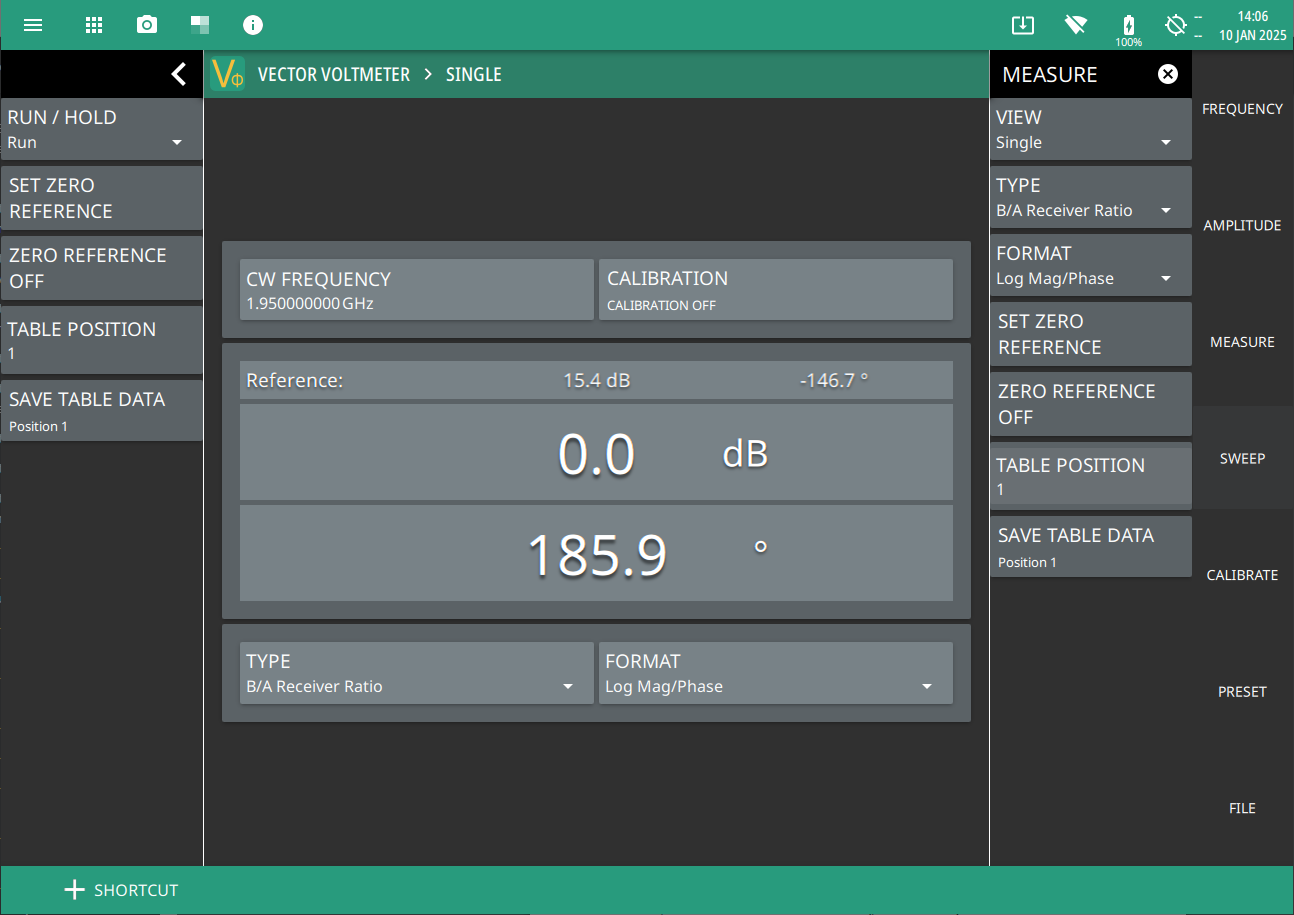
Log Mag/Phase
The magnitude of the voltage is expressed on a logarithmic scale and usually measured in dB. The Phase angle of the voltage is measured relative to a reference signal, typically expressed in degrees, as shown in Figure: Log Mag/Phase Measurement Format.
Log Mag/Phase Measurement Format
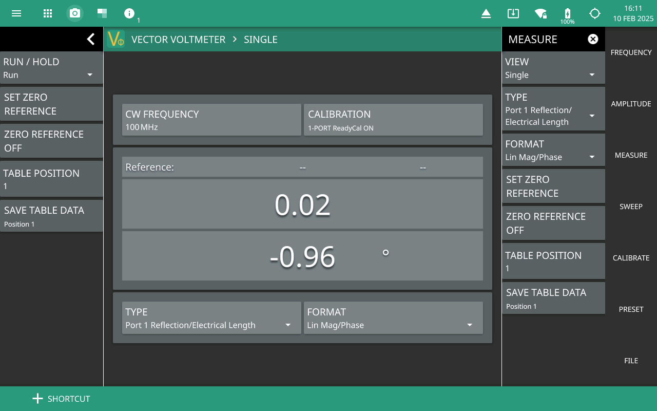
Linear Mag/Phase
The magnitude of the voltage is expressed in linear amplitude, without any logarithmic transformation. The phase angle of the voltage is measured relative to a reference signal, typically expressed in degrees, as shown in the Figure: Linear Mag/Phase Measurement Format.
Linear Mag/Phase Measurement Format
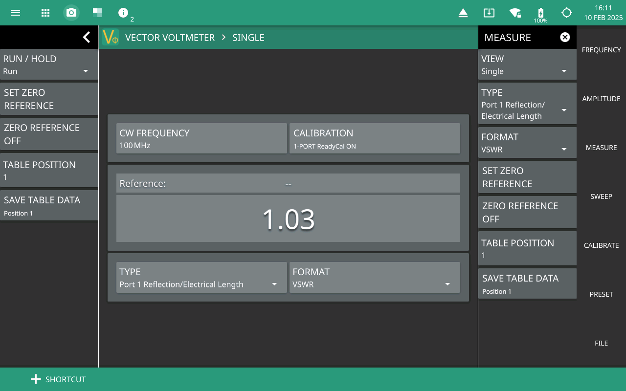
VSWR
The Voltage Standing Wave Ratio (VSWR) measurement format is essential for assessing the efficiency of transmission lines and antennas. VSWR indicates how well a load is matched to a transmission line, with implications for signal integrity and power transmission.The VSWR displays the ratio in the upper window only as shown in Figure: VSWR Measurement Format.
VSWR Measurement Format
Impedance
The impedance measurement format in a vector voltmeter provides essential data on how a circuit or device interacts with AC signals. By measuring voltage, current, and phase relationships, it allows for the calculation of complex impedance, which is critical for optimizing circuit performance in various applications. The Impedance measurement results are displayed as real impedance in the upper window, and as imaginary impedance in the lower window as shown in the Figure: Impedance Measurement Format.