 |
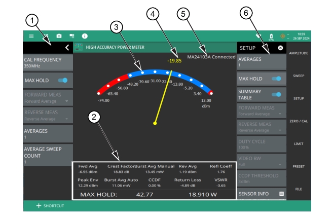
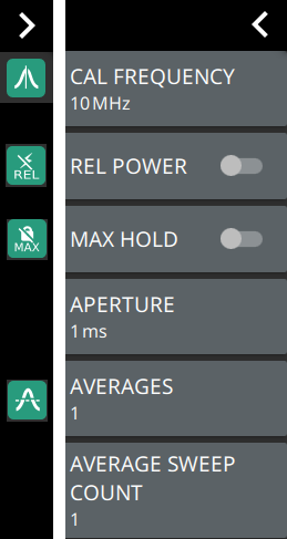
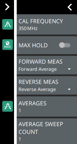
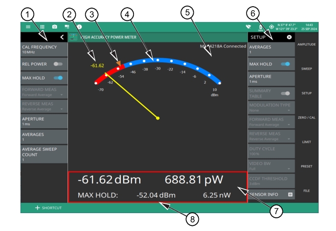
1. The status panel provides quick access to common settings used for power meter measurements. Refer to Status Panel. 2. The current power measurement (in dBm or watts) or the current relative power in dB or percentage. The number here tracks the analog meter pointer for normal USB power sensors. 3. The MAX HOLD marker indicated by a brown arrow head indicates the maximum power value. The max hold value is also displayed in the table below the meter. 4. The limits indicated by red/blue transitions on the meter denote the upper and lower limit values. When the pointer is in the blue region it indicates that the measured power is under the set limits and the measurement is passing; when the pointer is in the red region, the measurement is failing the limit. 5. The connected sensor model number and status is displayed here. 7. The measurement table shows the current and max hold power measurements in both dBm and watts, or relative power in dB and percent (%). for normal USB power sensors. 8. The measurement table border is shown in red for failing limits or green for passing limits. |