This chapter describes calibration methods and procedures using the SSLT calibration algorithm.
The SSLT calibration differs from an SOLT calibration by the differing offset lengths between two shorts which are used to help define reflection behavior instead of an open and short. Because of this, the frequency range is limited since, at DC and at higher frequencies, these reflect standards will look the same. This method is most commonly used for waveguide problems where creating a stable, high reflection open standard is difficult, but there are certain coax and board-level or wafer-level situations where it is useful. The modeling constructs are about the same as for an SOLT calibration. From an error term perspective, the only difference is that the two shorts together now largely determine source match and reflection tracking behavior.
The electrical length difference between the shorts should be between 20 and 160 degrees over the frequency range of interest.
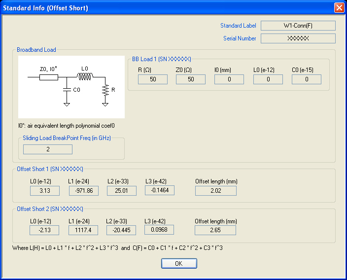
The top calibration kit definition dialog box for SSLT calibration is identical to the SOLT dialog (Figure: TWO PORT CAL SETUP (SOLT/R, COAXIAL) Dialog Box). The standards information dialog box is different and is shown below.
STANDARD INFO (OFFSET SHORT) Information Dialog Box
Typical parameters for Offset Short Calibrations
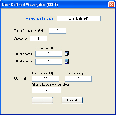
Variations for other line types (waveguide or microstrip) are similar to those for SOLT. For waveguide, the media and standards information are combined as shown in Figure: Waveguide Media and Standards Information. Defined, un-editable values would be present for Anritsu-defined cal kits.
Waveguide Media and Standards Information
Typical parameters for an Offset Short Calibration
A simplified short model is used for waveguide, with only an offset length and no inductance terms since usually those terms are small.