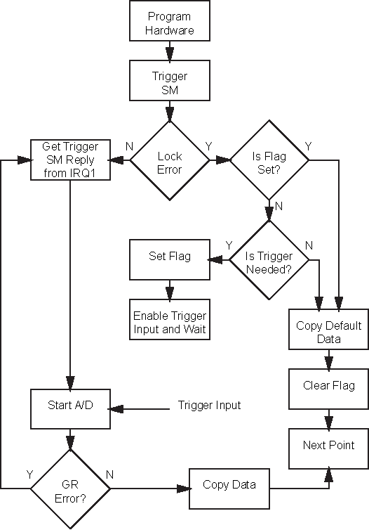
The MS4640A trigger system is used to synchronize analyzer actions with software trigger commands. The VNA follows the layered trigger model used in SCPI instruments. The following paragraphs describe the operation of the analyzer’s trigger system. A sample logic flowchart of the trigger model is shown in Figure: Triggering Logic Flowchart. A sample timing reference of the trigger model is shown in Figure: Sample Trigger Model.
Trigger Modes
The trigger system supports four different trigger modes:
• Internal Trigger Mode
This is an automatic triggered point-by-point measurement that is internally controlled by the DSP software.
• Manual Trigger Mode
Manual mode is triggered by the user from the front panel to start a measurement based on a per point, a per sweep (or a per port), or a per channel (or all channels) trigger mode.
• GPIB Trigger Mode
GPIB mode is triggered by a GPIB trigger command to start a measurement based on a point-per-point, a sweep-per-sweep (or a port-per-port), or a channel-per-channel (or all channels).
• External Trigger Mode
• External mode is triggered through the rear panel input of the instrument to start a measurement based on a point-per-point, a sweep-per-sweep (or a port-per-port), or a channel-per-channel (or all channels) trigger mode.
• The external trigger system allows the user to select a positive or negative edge trigger to start the measurement.
• A trigger delay can also be applied to a measurement right after an external trigger is received by the instrument and just before the measurement begins.
• The external trigger has an additional feature to handle trigger handshaking, which uses the “Ready for Trigger” and “Trigger Output” output signals through the rear panel of the instrument.
• The Ready for Trigger signal is sent from the instrument to the rear panel output when the system is ready to accept an external trigger.
• The Trigger Output pulse signal is sent to the rear panel when the system has completed a measurement.
The following diagram is a flowchart of the triggering logic:
Triggering Logic Flowchart
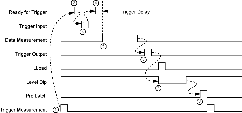
Trigger Timing
The timing diagram below illustrates the general measurement sequence of per-point triggering using a positive trigger edge. Trigger Delay, Ready for Trigger, and Trigger Output are only used by an external trigger.
Sample Trigger Model
The trigger sequence with trigger handshake turned on is as follows (Trigger Handshake enables “Ready for Trigger” and “Trigger Output”:
1. A trigger measurement is received from the State machine.
2. Ready for Trigger (rear panel BNC output) is set to low to indicate that the instrument is ready for trigger.
3. External trigger (rear panel BNC input) is received.
4. After the external trigger is received, the Ready for Trigger (rear panel BNC output) is set to high to indicate that the system is not ready for trigger and the trigger delay is added.
5. The data measurement is started.
6. At the completion of the data measurement, the Trigger Output (rear panel BNC output) is pulsed to indicate that the measurement is completed.
7. The Level Dip and/or the LLoad pulse are executed.
8. The next frequency is preloaded and the State machine is triggered.
Note
Trigger handshaking is enabled with:
:TRIGger[:SEQuence]:EXTernal:HANDshake[:STATe]
If handshaking is not in use, steps 2, 4, and 6 are deleted, but the trigger delay is still present.