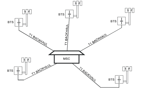
Wireless service providers use wired T1 circuits as the backhaul links to connect a Base Transceiver Station (BTS) to a Mobile Switching Center (MSC). The quality of the service that is provided over those T1 lines has a direct impact on the quality of service that is experienced by the wireless service provider customers. Call setup failures, dropped calls, and data errors can often be attributed to the T1 backhaul facilities. An example of a typical wireless network backhaul T1 link is shown in Figure: Typical Wireless Network T1 Backhaul Links.
In the United States, wireless service providers generally lease T1 lines from a Local Exchange Carrier (LEC), so a joint effort is often required to analyze and troubleshoot a T1 line.
T1 is an American National Standard Institute (ANSI) standard, used mostly in North America, in parts of Japan, and in some Asian countries. Technically, a T1 line is a digital transmission facility consisting of wire pairs and regenerators carrying a DS1 signal. T1 refers to the physical properties of the line, for example, 1.544 MHz with a specific pulse shape, and so forth. DS1 refers to the digital signal carrying the information at a rate of 1.544 Mb/s.
A DS1 signal contains twenty‑four 8‑bit DS0 channels. The channel signals are repeated 8000 times per second, resulting in a bandwidth of 64 kHz per channel (8 x 8000 = 64,000). The channels are organized into 192-bit frames, and a framing bit is added to enable synchronization to the DS1 signal (193 bits total). The frequency of the T1 signal is 193 x 8000 = 1.544 MHz. Two types of DS1 framing formats are used: Super Frame (SF), formed from 12 basic frames, and Extended Super Frame, formed from 24 basic frames.
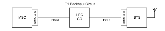
The circuit between the MSC (Mobile Switching Center) and BTS (Base Transceiver Station) may pass through the LEC central office (see Figure: BTS and MSC Configuration), or through multiple central offices. It may also pass through multiple pieces of transmission equipment. At the BTS, the T1 line typically terminates on a Network Interface Unit (NIU). The NIU may be a very simple device having only a remote loop back capability, or it may provide very sophisticated performance monitoring capabilities. Its capabilities may or may not be accessible to the wireless service provider technician.
Some repeaters may exist in the circuit when the signal is traveling long distances. Repeaters are full duplex devices that regenerate or restore the pulse shape and amplitude. Two possible network topologies are shown in Figure: One Possible T1 Network Topology and Figure: BTS and MSC Configuration.
BTS and MSC Configuration
The configuration in Figure: BTS and MSC Configuration uses a High‑speed Digital Subscriber Line (HDSL) in the T1 circuit, which enables full duplex T1 service over a single pair of wires without repeaters. In most cases, the wireless service provider technician may not be concerned with the repeaters or HDSL.