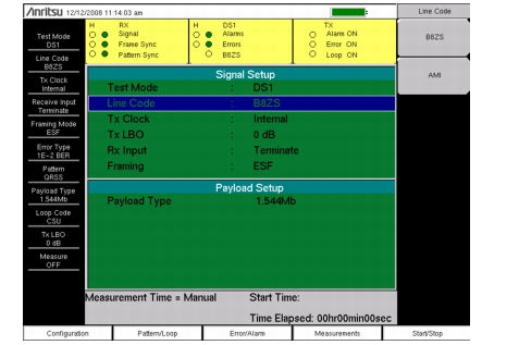
Refer to Figure: T1 Display Screen for an illustration of the following areas of the instrument display screen. The T1 data display area of the instrument includes the real time clock and the GPS and battery indicators (at the top), the measurement data (in the middle), the instrument settings summary (at the left side), the submenu labels (at the right side), and the main menu labels (at the bottom). The submenu labels vary in relation to the main menu key selection.
In T1 measurements, the instrument settings summary shows the T1 configuration, including: Test Mode, Line Code, Tx Clock, Receive Input, Framing Mode, Error Type, Pattern, Payload Type, Loop Code, Tx LBO, and Measure.
The upper part of the measurement data display has an area that is highlighted in yellow, which reports historical (H) and current pass/fail conditions for parameters relating to Rx (Receive), DS1, and Tx (Transmit) testing. For Rx, the parameters are Signal, Frame Sync, and Pattern Sync. For DS1, the parameters are Alarms, Errors, and B8ZS. For Tx, the parameters are Alarm ON, Error ON, and Loop ON.
T1 Display Screen
The columns of historical data (for Rx and DS1) are labeled with an H. The adjacent columns display current (present time) conditions. The B8ZS indicator for DS1 displays only the current condition (no historical data). The H indicators turn red when an error has occurred previous to the current pass/fail condition. These error indications are cleared by pressing the Clear History submenu key in the Measurements menu. The Tx column indicators display ON/OFF status for Alarm, Error, and Loop testing.
The remainder of the measurement display is used for setups, configurations, and measurement display, which changes with the selected function.
The T1 function main menu keys are: Configuration, Pattern/Loop, Error/Alarm, Measurements, and Start/Stop.