In-service testing can be done only when the equipment has a test port. When testing a T1 circuit that is in service, the access to the circuit must be bridged via a monitor port in order to avoid disrupting service. Even when the T1 circuit is down, these tests will help to verify and identify the correct fault circuit. The following measurements can be used to check the T1 performance during regular maintenance:
• Vpp Measurement
• Carrier
• Frame Sync
• CRC Errors, for Extended Super Frame (ESF)
• BPV
• Frequency
Required Equipment
• Bantam Cables, Anritsu Part Number 806‑16
Measurement Setup Procedure
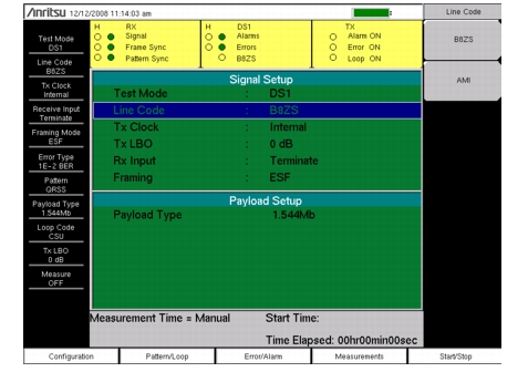
1. While in the T1 Analyzer mode, press the Configuration main menu key.
2. Use the Up/Down arrow keys or the rotary knob to highlight Test Mode and select DS1.
3. Use the Up/Down arrow keys or the rotary knob to highlight Line Code and press the B8ZS or AMI line coding submenu key.
4. Use the Up/Down arrow keys or the rotary knob to highlight Tx Clock and select Internal, Recovered, or External. For more Tx Clock information, refer to TxClock: Internal, External, Recovered.
5. Use the Up/Down arrow keys or the rotary knob to highlight Rx Input and press the Bridge or Monitor submenu key, as appropriate for the connection.
Note
If Monitor access is pressed, 20 dB of gain is added to the receive path. The Bridge or Monitor selection must be made before the instrument is connected to the circuit.
6. Use the Up/Down arrow keys or the rotary knob to highlight Framing and press the ESF or SF‑D4 framing submenu key.
Note
The setup parameters are displayed in the instrument settings summary on the left side of the screen. The status window on the top of the screen is always displayed.
7. Connect the Rx cable to one of the pairs.
8. Press the Measurement main menu key, then the BERT submenu key, then the Table submenu key. Press the Start/Stop main menu key to activate the measurement.
9. Verify Rx Signal, Frame Sync, CRC, and BPV.
10. Press Rx Signal submenu key (Measurements menu) and verify Vpp and Frequency. When very close to the Tx source, the signal should be between 4.8 Vpp and 7.2 Vpp. The frequency should be 1.544 MHz ± 50 Hz (± 32 ppm).
11. Move the Rx connection to the other pair on the circuit under test and then repeat the tests.
Note
Screen captured images are provided as examples. The image and measurement details shown on your instrument may differ from the examples in this user guide.