The main menu keys and submenu keys for Distance‑to‑PIM™ analysis differ from the PIM Analyzer menus as described in PIM Analyzer. For a description of the key functions in the Distance‑to‑PIM™ menus, refer to section Menu Map.
Note
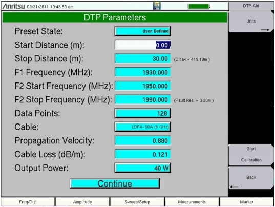
Anritsu handheld instruments with a touch screen offer additional options for some features. You can touch a submenu key or a screen feature (such as the button for the Preset State entry in the DTP Parameters window shown in Figure: DTP Parameters Window).
1. Press the Measurements main menu key to display the Measurements menu.
2. Press the Distance‑to‑PIM submenu key.
3. Press the Freq/Dist main menu key.
4. Press the DTP Aid submenu key to set up the DTP measurement parameters. The DTP Parameters setup window is displayed, and the DTP Aid menu is displayed.
DTP Parameters Window
5. In the DTP Parameters window, highlighting the Preset State button displays the Preset State menu. Press the Preset State List submenu key (or touch the Preset State button on the screen) to open a list box. Select from the list of preset states (with differing frequencies and output powers). The Preset State that is shown in Figure: DTP Parameters Window is set to User Defined. When this touch‑screen button or the Preset State List submenu key is pressed, the Select DTP Preset State list box is displayed on screen. Use an arrow key or the rotary knob to highlight a selection, and then press the Enter key. The menu display returns to the DTP Aid menu. Refer to Preset State Definitions for a list of the available preset states.
6. From the DTP Aid menu, press the Units submenu key to display the Units submenu. Press the Meters or Feet submenu key to select the desired units to be used in the measurement. The menu display returns to the DTP Aid menu.
7. Highlight one of the distance setting buttons. Use the numeric keypad to set the Start and Stop distances. The Units menu is displayed with a submenu key for either meters or feet, depending upon the units setting (from the DTP Aid menu Units key).
The Stop Distance needs to be smaller than Dmax. Dmax is the maximum horizontal distance that can be analyzed. The Stop Distance cannot exceed Dmax. If the cable is longer than Dmax, then Dmax needs to be improved by increasing the number of data points or by lowering the frequency span (ΔF).
Note that the number of data points can be set to either 64 points or 128 points. The number of data points should always be set to the maximum amount of steps available, with respect to the F2 swept bandwidth. When the start and stop distances have been set, the menu display returns to the DTP Aid menu.
8. Highlight (or touch) the Data Points button to open the Resolution menu. Select the number of data points that best fits the measurement: 64 points or 128 points.
9. Enter a value for F1 Stationary Frequency (MHz).
10. Enter the F2 Swept Frequency (F2 Start Frequency and F2 Stop Frequency).
Note
Carrier frequencies F1 and F2 must be separated by a minimum of 20 MHz for the MW8219A and by a minimum of 10 MHz for the MW8209A and the MW8208A.
For example:
F2 Start – 20 MHz must be greater than or equal to F1 (MW8219A)
F2 Start – 10 MHz must be greater than or equal to F1 (MW8209A)
11. Highlight (or touch) the Cable button to display the available cable specifications. Use the Standard List submenu keys along with the rotary knob to navigate to the desired cable specification, and then press Enter (or press the Esc key to abort without selecting a cable).
Note
When a cable is selected from this list, propagation velocity and cable loss are automatically set by the instrument.
12. If the Cable selection is “None”, then, for the cable in use, enter an applicable Propagation Velocity and enter an applicable Cable Loss value in dB/ft or dB/m.
13. Highlight (or touch) the Output Power button to open the Select PIM Output Power list box. Select an appropriate power level and press Enter.
14. Press the Continue button and, if the Anritsu handheld instrument is calibrated, then continue with Step 15. Otherwise, follow the calibration instructions in DTP Testing Calibration, and then return to this procedure (before connecting the device under test (DUT) to the PIM Master) and continue with Step 15.
Note
The DTP Analyzer includes several menus with buttons for setting up measurement parameters. All of these parameter settings are also available in one convenient location in the DTP Parameters window, which is opened by pressing the DTP Aid submenu key.
15. Press the More submenu key to open the DTP Setup menu.
16. Press the Window submenu key to open the Windowing menu. Select the desired windowing format by pressing one of the four submenu keys – Rectangular, Nominal Side Lobe, Low Side Lobe, and Minimum Side Lobe. Refer to Windowing.
17. Press the Measurements main menu key. Then press the Test submenu key to begin your measurement.
If you need to terminate the measurement before the allotted Test Duration time is complete, then you can press the Test submenu key to turn off the measurement. Also, RF power can be immediately turned off with the Emergency Stop button on the PIM Master (Item 2 in Figure: PIM Master Connector Panel).