To run a BBU test, follow the steps described below. It is assumed that any needed scripts such as BBU scripts and LTE waveform patterns have been downloaded to the Anritsu instrument internal memory, as described in the previous sections.
1. For accurate measurements, select an external frequency reference or establish a GPS location fix for your instrument before entering BBU Emulation mode.
2. Follow instructions in the CPRI Configuration Example to set up the Anritsu instrument for the RRH you plan to test.
3. From the CPRI mode Measure menu, press BBU Emulation. The Anritsu instrument’s SFP port will go from slave to master mode.
4. If not connected, connect the instrument SFP to the RRH slave port using a suitable fiber cable.
5. Press Select Initialize RRH to start auto-negotiating the line rate with the RRH and establish a CPRI connection to the passive layer.
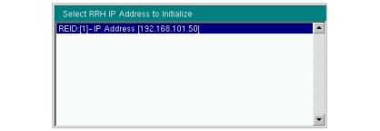
If multiple radios are connected in a daisy chain, the Anritsu instrument assigns an IP address to each, using its built-in DHCP server. It may take a few minutes for the instrument to gather RRH IP information, then a pop-up window is displayed, listing the RRHs that responded.
RRH IP Address List
6. Choose the desired IP address from the displayed list, then press Enter.
7. A message box is displayed while information on the selected RRH is collected.
Attention Message Box
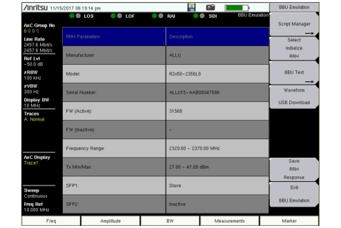
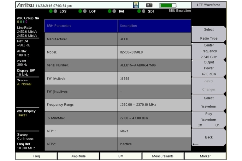
8. Review the displayed RRH parameters as needed.
RRH Parameter Display
9. Press BBU Test. Note that this key is active only after you have initialized the RRH in the preceding steps.
11. To remotely monitor and control RET devices through the RRH, proceed with RET Test.
To perform RRH-based measurements, skip to BBU RF Test.
RET Test
The following instructions assume that you have loaded any necessary scripts and successfully connected to an RRH as described in the previous sections. Refer to RET Test Menu for a description of individual menu keys.
Note
Option 761 is required to perform RET Test. Without the option installed and activated, you can only scan for and update the status of connected devices.
1. Press RET Test under the BBU Test menu.
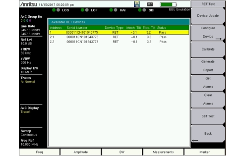
The instrument automatically scans for all RET devices connected to the selected RRH, then displays their current status on the instrument screen. See Figure: Available RET Devices.
If no RET devices are found, a “No Devices Detected” message will display. You can optionally press the Device Update key to perform another scan.
Available RET Devices
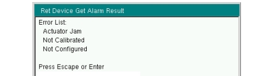
2. If all detected devices show “Pass,” skip to Step 5. If a device displays a “Fail” status, use the Up/Down arrow keys, rotary knob or the touch screen to highlight, that is, to select it, then press Get Alarms. Only one device can be selected at any time.
Get Alarm Results
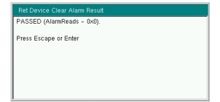
3. Press Clear Alarms to attempt and clear the error(s). A message will display, indicating whether the attempt was successful.
Clear Alarm Results
4. If alarms remain after the clearing attempt, take the necessary corrective actions. You can also initiate a self-test on the selected device by pressing the Self Test key.
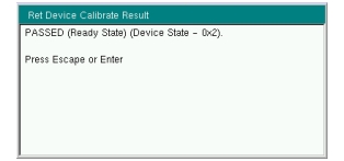
5. If needed, select a RET device, then press Calibrate to make the actuator move through its entire tilt range, thus determining the minimum and maximum electrical tilts. A calibration result window will display when the action is completed.
Device Calibration Results
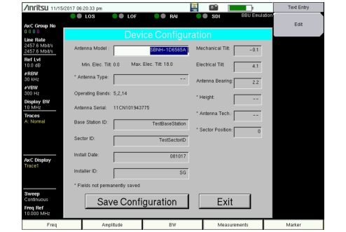
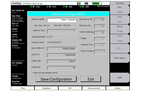
6. Press Configure Device to display the configuration form. Some fields are pre-populated with the current configuration settings of the RET device. See Figure: RET Device Configuration Dialog.
7. Proceed through the next steps only if you need to make configuration changes. Otherwise, press Exit to return to the RET Test menu, then skip to Step 14.
Note
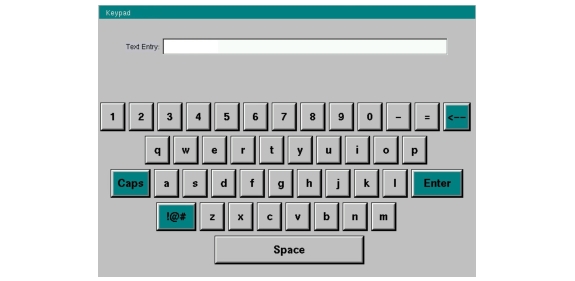
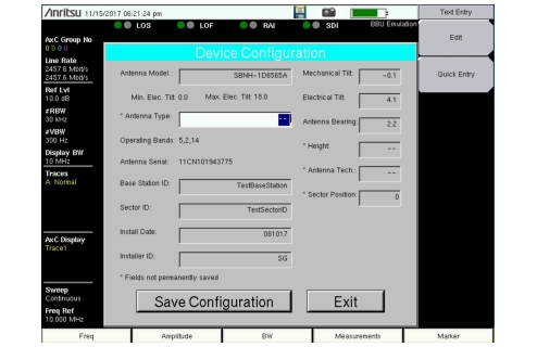
To edit a configuration field, use the touch screen, rotary knob, or Up/Down arrow keys to highlight it, then press the appropriate keys to change the value. Some of the fields are read-only.
The menu keys change depending on the data type of the current configuration field. Text entry methods are also different for instrument models with and without a touch screen.
Press Save Configuration to save current settings to the RET device. Saved settings will appear in configuration reports generated during this RET Test session. Fields marked with an asterisk (*) in the Device Configuration dialog are saved to the test instrument internal memory but cannot be permanently saved to the RET device, and are cleared when you exit RET Test mode.
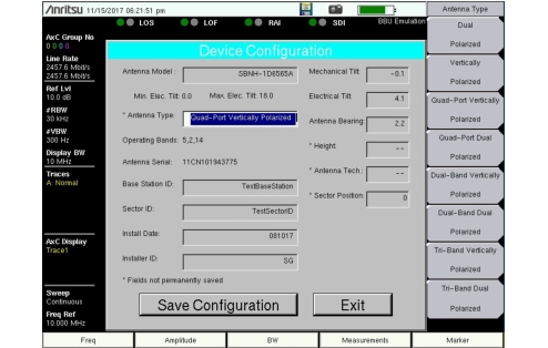
10. Configure other text fields in the same manner, using the Edit key or Quick Entry if present. For numeric fields, use the numeric keypad, then press Enter. The Antenna Height value is in meters. The Sector Position value ranges from 0 to 255.
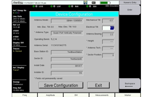
11. To adjust the antenna tilt angle, select the field and use the numeric keypad to enter a new value for the Electrical Tilt. The value must be within the valid tilt range (minimum and maximum). Press Enter to submit the new value.
Electrical Tilt Entry
12. Edit the remaining fields as needed, then press Save Configuration. The saved values will be listed in configuration reports that you generate during this RET Test session.
Newly entered settings are lost if you exit the Device Configuration dialog before saving them.
Note
Fields marked with an asterisk (*) are saved to the test instrument internal memory but cannot be permanently saved to the RET device. These fields are cleared when you exit RET Test mode:
Antenna Type Tower Height Antenna Technology Sector Position
13. Press Exit to close the Device Configuration dialog and return to the RET Test menu. The Available RET Devices window will display the updated device status.
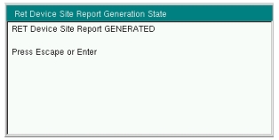
14. To output the current configurations of all detected RET devices to a text file, press the Generate Report key. The report file will be named with the current date and time and saved to the instrument’s internal memory.
Report Generation State
15. Press Back to return to the BBU Test menu.
BBU RF Test
The following procedure assumes that you have loaded any necessary scripts and successfully connected to an RRH as described in the previous sections.
1. Press BBU RF Test under the BBU Test menu.
2. Press LTE Waveforms.
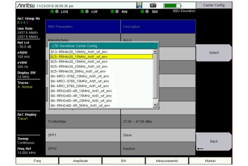
3. Press Select Radio Type and choose from the list the carrier configuration that matches the radio type and bandwidth of the signal you want to transmit through the RRH. Press Select.
LTE Waveform Carrier Configuration
4. Optionally, press the Center Frequency key under the LTE Waveforms menu and adjust the carrier frequency of the radio. The frequency defaults to the center frequency of the selected RRH transmit band.
5. You may also adjust the transmit power from the RRH using the Output Power key. The default power is 3 dB below the maximum output power of the RRH being tested.
6. Press Apply Changes to update the RRH configuration.
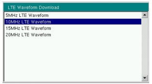
7. Press Select Waveform and select a bandwidth from the list, then press Enter.
LTE Waveform Bandwidth List
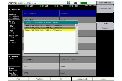
8. Scroll to the waveform corresponding to the radio type selected earlier, then press Select/Deselect to highlight it. One waveform pattern may be transmitted at a time.
LTE Waveform Select
9. Press the Enter key to load the selected waveform.
10. Wait for the message indicating that loading was successful, at which point the Play Waveform key on the LTE Waveforms menu will become active.
11. Press Play Waveform to turn on the transmitter and send the waveform to the RRH.
Play Waveform
12. Stand in front of the desired antenna with a spectrum analyzer and you should see the waveform transmitting from the antenna.
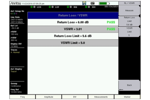
13. Press Back to return to the BBU RF Test menu, then press Return Loss/VSWR. Provided the RRH is transmitting, test results are displayed on the instrument screen.
Returm Loss/VSWR Measurement Results
14. You can optionally change the return loss limit and VSWR limit and press Measure to run the test again.