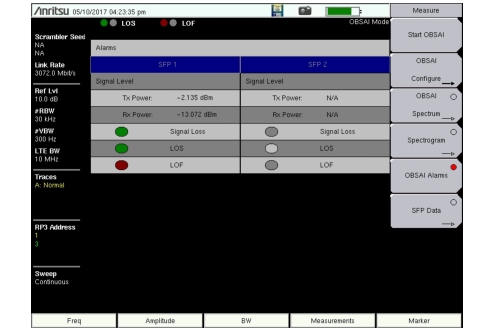
 | Start OBSAI Press this key to initiate a scan of the OBSAI links for active RP3 addresses and detect the link rate. When Start OBSAI finds one or more valid RP3 addresses, the display will reset to a single Spectrum graph with Carrier Trace 1 displaying the first available RP3 address in the list. The display bandwidth is set to match the LTE bandwidth of Trace 1. To display additional traces (up to four), go to Carrier Trace Config Menu, select the trace number, then choose Display 1 or 2 and select an RP3 address. The RP3 address list is empty following an instrument power cycle or when no OBSAI carriers are found. You must then plug in a new OBSAI link or run a scan with Start OBSAI to obtain valid address entries. OBSAI Configure Opens the OBSAI Config Menu. OBSAI Spectrum Press this key to select the OBSAI spectrum view. Depending on the current display mode, you may have to press the key a second time to open the OBSAI Spectrum Menu. Spectrogram Press this key to select the spectrogram view and open the Spectrogram Menu. OBSAI Alarms Displays the SFP port alarm status and the Tx and Rx optical power levels. See Figure: OBSAI Alarms Screen (dual-SFP Model Is Shown) for an example of a dual-SFP display. “Pass” status is shown as green; “Fail” is red. Colors may appear differently depending on the display settings. No color, or grey, means there is no connection at the SFP port. SFP Data Opens the OBSAI SFP Data Menu. |