The Open Base Station Architecture Initiative (OBSAI) specifications define a set of requirements for a wireless base transceiver station (BTS). Reference Point 3 (RP3) within the OBSAI specifications defines the digital interface between the Base Band Module (BBM) and the Radio Frequency Module (RFM). This is an alternative to the traditional Radio Frequency (RF) coaxial connection, or the CPRI digital interface.
Anritsu’s OBSAI Analyzer (Option 753) allows users to make RF-based measurements over a fiber optic OBSAI link to look for interference problems affecting an RFM. This is accomplished by tapping into the fiber link between the RFM and BBM, using an optical splitter to connect to the Anritsu test instrument. The instrument will decode the OBSAI protocol IQ data and convert it to RF data.
Note
Option 753 requires Option 759, RF over Fiber Hardware. Depending on your Anritsu test instrument model, Option 759 may have a single or dual SFP ports. Refer to your instrument Technical Data Sheet for specifications.
Screen displays vary with the installed option and instrument model being used. The screen captures illustrated in this document are examples and may differ from your instrument display.
• Spectrum mode is typically used to test the OBSAI link in real time.
• Spectrogram mode lets users monitor for intermittent interference over a specifiable recording time.
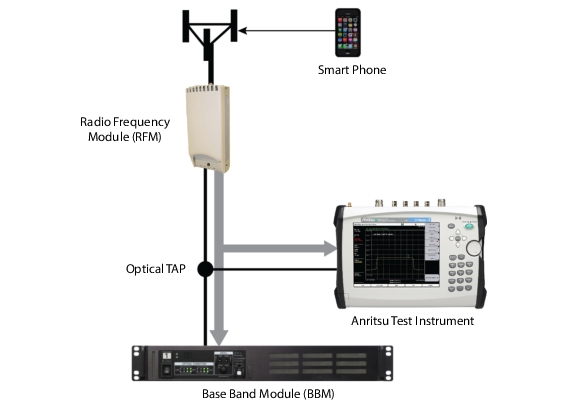
These OBSAI Analyzer test and measurement functions can be performed from ground level, eliminating the risk and costs of climbing towers. Figure: Connection Configuration for OBSAI Testing with Anritsu Test Instrument illustrates a typical connection configuration for OBSAI testing with an Anritsu test instrument.
Connection Configuration for OBSAI Testing with Anritsu Test Instrument