DTF reveals the precise fault location of components in the transmission line system. This test helps to identify specific problems in the system, such as connector transitions, jumpers, kinks in the cable or moisture intrusion.
To measure the distance of a cable, DTF measurements can be made with an open or a short connected at the end of the cable. The peak indicating the end of the cable should be between 0 dB and 5 dB. An open or short should not be used when DTF is used for troubleshooting because the open/short will reflect everything and the true value of a connector might be misinterpreted and a good connector could look like a failing connector.
A 50 Ω load is the best termination for troubleshooting DTF problems because it will be 50 Ω over the entire frequency range. The antenna can also be used as a terminating device but the impedance of the antenna will change over different frequencies because the antenna is only designed to have 15 dB or better return loss in the passband of the antenna.
DTF measurement is a frequency domain measurement and the data is transformed to the time domain using mathematics. The distance information is obtained by analyzing how much the phase is changing when the system is swept in the frequency domain. Frequency selective devices such as TMAs (Tower Mounted Amplifiers), duplexers, filters, and quarter wave lightning arrestors change the phase information (distance information) if they are not swept over the correct frequencies. Care needs to be taken when setting up the frequency range whenever a TMA is present in the path.
Because of the nature of the measurement, maximum distance range and fault resolution is dependent upon the frequency range and number of data points. DTF Aid shows how the parameters are related. If the cable is longer than DMax, the only way to improve the horizontal range is to reduce the frequency span or to increase the number of data points. Similarly, the fault resolution is inversely proportional to the frequency range and the only way to improve the fault resolution is to widen the frequency span.
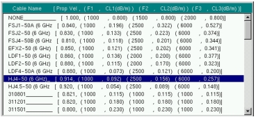
The instrument is equipped with a cable list (Figure: Cable List) including most of the common cables used today. Once the correct cable has been selected, the instrument will update the propagation velocity and the cable attenuation values to correspond with the cable. These values can also be entered manually. Custom Cable lists can also be created with Line Sweep Tools or Master Software Tools and uploaded into the instrument. Incorrect propagation velocity values affect the distance accuracy and inaccurate cable attenuation values affect the accuracy of the magnitude value.
Cable List
Fault Resolution
Fault resolution is the system's ability to separate two closely spaced discontinuities. If the fault resolution is 10 feet and there are two faults 5 feet apart, the instrument will not be able to show both faults unless Fault Resolution is improved by widening the frequency span.
Fault Resolution (m) = 1.5 x 10⁸ x vp / ΔF
where vp is the propagation velocity of the transmission cable as discussed in the previous section.
Time Delay
The 5GNR standard specifies a minimum time delay in a measurement system, so wireless carriers need to know the time delay generated by the various coax connections and components used in their network deployment. The Time Delay measurement allows users to measure the signal propagation delay through the coaxial transmission system between the Start distance and an active marker, or between an active delta marker and its reference. Refer to Markers for information on using markers.
DMax
DMax is the maximum horizontal distance that can be analyzed. The Stop Distance can not exceed Dmax. If the cable is longer than Dmax, Dmax needs to be improved by increasing the number of data points or lowering the frequency span (ΔF). Note that the data points can be set to 137, 275, 551, 1102, or 2204
Dmax = (Datapoints – 1) x Fault Resolution
DTF Setup
1. Press the Measurements main menu key and select DTF Return Loss or DTF VSWR.
2. Press the Freq/Dist main menu key.
3. Press the Units submenu key and select m to display distance in meters or ft to display distance in feet.
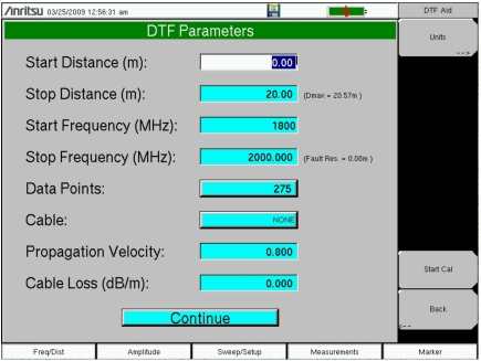
4. Press DTF Aid and use the touch screen, or arrow keys to navigate through all the DTF parameters.
a. Set Start Distance and Stop Distance. Stop Distance needs to be smaller than Dmax.
Note
If Stop Distance is greater than DMax, increase the number of data points.
b. Enter the Start and Stop frequencies.
c. Press Cable and select the appropriate cable from the cable list (Figure: Cable List).
d. Press Continue.
5. Press Shift and Calibrate (2) to calibrate the instrument. See Calibration for details.
6. Press the Marker main menu key and set the appropriate markers as described in Markers.
7. Press Shift and Limit (6) to enter and set the limits as described in Limit Lines.
8. Press Shift and File (7) to save the measurement. See the User Guide for details.
DTF Aid
Example 1 – DTF Transmission Line Test
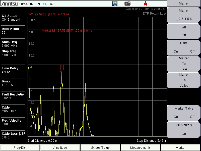
The Distance-To-Fault transmission line test verifies the performance of the transmission line assembly and its components and identifies the fault locations in the transmission line system. This test determines the return loss value of each connector pair, cable component and cable to identify the problem location. This test can be performed in the DTF-Return Loss or DTF-VSWR mode. Typically, for field applications, the DTF-Return Loss mode is used. To perform this test, disconnect the antenna and connect the load at the end of the transmission line.
Typical Passing DTF Return Loss Measurement
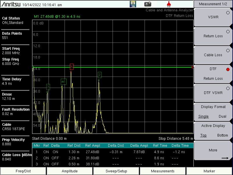
Typical Failing DTF Return Loss Measurement
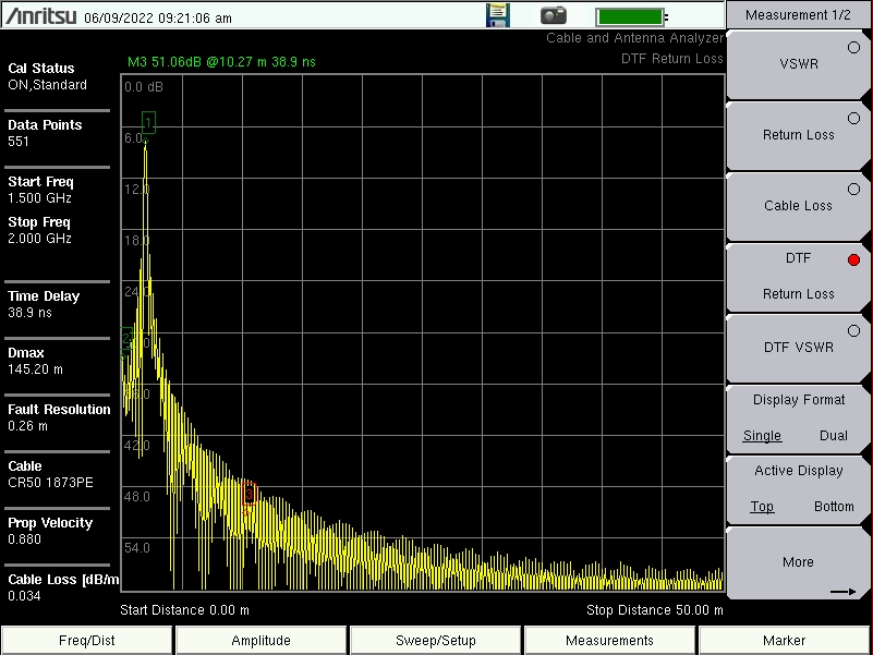
Example 2 – DTF with a short
To measure the distance of a cable, DTF measurements can be made with an open or a short connected at the end of the cable. The peak indicating the end of the cable should be between 0 dB and 5 dB.
Typical DTF Return Loss Measurement with a Short at the End of the Cable