The PIM over CPRI feature in the CPRI LTE RF application is available with Option 754. It allows your Anritsu test instrument to detect and measure interference from Passive Intermodulation (PIM) on LTE signal carriers. Measurements are made via a CPRI connection over optical fiber, using live traffic data. This is in contrast to other PIM measurement solutions that use RF tones to create PIM in the RF network under test, which may be in violation of local regulations restricting the transmission of test tones on a live network.
Note
Option 754 is not supported on all instrument models. It requires Option 752, CPRI LTE RF Analyzer, and Option 759, RF over Fiber Hardware (dual SFP ports). Refer to your instrument’s Technical Data Sheet for option availability.
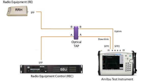
By inserting optical taps between the BBU and RRH for the uplink and downlink carriers, you can measure PIM without the need to take the system out of service. This eliminates the potential for PIM that might result if it were necessary to reset RF connections.
Unlike traditional RF PIM analyzers, which must be taken to the top of cell towers or close to the antenna to run measurements, Anritsu’s PIM over CPRI software option enables true PIM measurements from ground level, increasing site safety while speeding up network performance validation.
• Single carrier 2x2 MIMO LTE interfering with its own uplink (self-PIM interference) – An example may be a 10 MHz LTE carrier downlink centered at 751 MHz with 7th order intermodulations that fall in the 782 MHz uplink band.
Self-PIM Interference Test Instrument Connection
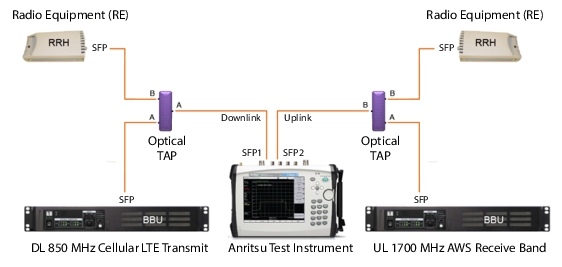
• Single carrier 2nd order intermodulation (2nd harmonic) – Examples may be a an 850 MHz cellular transmitter’s 2nd harmonic landing in the 1700 MHz AWS receive band, or an 860 MHz cellular transmitter’s harmonic falling in a 1720 MHz AWS uplink band.
2nd Harmonic Test Instrument Connection
PIM Over CPRI Configuration Settings
Before starting the PIM measurement, choose the appropriate settings in each of the following configuration categories:
• Site configuration
• PIM desensitization limit
• Downlink configuration
• Uplink configuration
• Uplink under test
Note
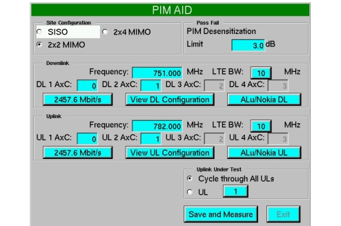
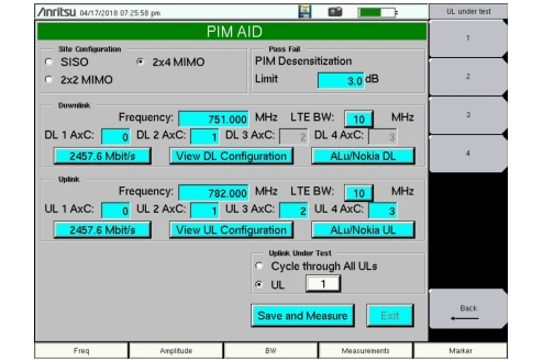
These parameters are set in the PIM Aid configuration dialog. See Figure: PIM Aid Dialog. When saved, the selections made here override any conflicting settings previously chosen in the CPRI configuration, such as line rate, display bandwidth, and uplink AxC group and SFP port associations.
Site Configuration
Anritsu’s PIM over CPRI feature supports analysis of up to four simultaneous CPRI streams.
• SISO – Single downlink, single uplink
• 2x2 MIMO – 2 downlinks, 2 uplinks
• 2x4 MIMO – 2 downlinks, 4 uplinks
The CPRI downlink is connected to the Anritsu test instrument’s SFP Port 1. The uplink is connected to SFP Port 2.
PIM Aid Dialog
PIM Desensitization Limit
This is the user-selectable threshold for acceptable noise floor degradation, in dB. A measurement that exceeds the set limit will result in a Fail status and trigger the alarm.
Frequency
The Frequency fields for downlink and uplink accept numeric values and are edited using the instrument keypad. The values entered are in MHz.
LTE Bandwidth
The downlink and uplink LTE bandwidths are selectable from a menu of four supported LTE carrier bandwidths: 5 MHz, 10 MHz, 15 MHz, and 20 MHz. The applied uplink bandwidth will display on the left side of the trace window.
AxC Group
Use the AxC fields to associate an AxC group number with each downlink and uplink trace. The number of configurable traces depends on the selected site configuration.
Line Rate
The Line Rate buttons in the Downlink and Uplink sections of the PIM Aid dialog show the respective line rates currently selected. The buttons also function as Auto Detect keys and will display the actual downlink or uplink line rates anytime they are pressed.
When applied, the downlink (SFP Port 1) and uplink (SFP Port 2) line rates are displayed on the left side of the instrument screen.
Radio Preset
Radio presets are currently available for ALu/Nokia.
View Downlink/Uplink Configuration
Press the View DL Configuration or View UL Configuration button to apply the current settings and display the downlink or uplink traces, respectively. The PIM Aid dialog will close without exiting Configuration mode.
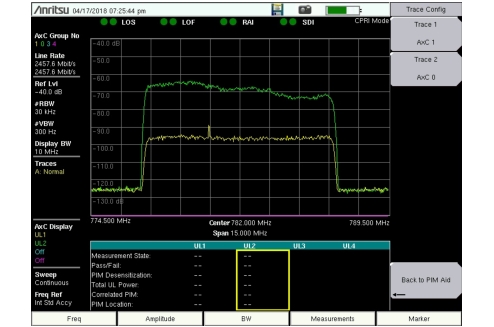
The number of traces displayed is determined by the chosen site configuration. For example, one trace is displayed if the configuration is SISO, and two downlinks or four uplinks in 2x4 MIMO. Figure: View Uplink Configuration Example illustrates two uplink traces in 2x2 MIMO.
To change the AxC group number for a trace, press the desired Trace number key under the Trace Config menu and edit the AxC group.
Press the Back to PIM Aid key to return to the configuration dialog.
View Uplink Configuration Example
Uplink Under Test
During PIM measurements, the Anritsu test instrument displays only the Uplink Under Test and the Correlated PIM as Trace 3 and Trace 4, respectively. Trace 1 and Trace 2 are off.
In 2x2 and 2x4 MIMO, you can elect to cycle through all uplinks or measure only one uplink. Choosing Cycle through All ULs will measure all available uplinks one at a time. To measure a single uplink, press the UL radio button (see Figure: Select Uplink Under Test), then the UL number box to display the UL Under Test menu, and press the desired uplink number.
Select Uplink Under Test
Save and Measure
To save the current configuration settings and start PIM over CPRI measurements, press the Save and Measure button.
Exit
Press the Exit button or the instrument panel Esc key to close the PIM Aid dialog without making changes.
Important
The Exit button is active only if you have not made a change in the PIM Aid dialog. The button is disabled (grayed out) if you have modified one of the configuration fields. For all configuration settings to be applied properly to the PIM over CPRI measurements, use the Save and Measure button.
PIM Configuration and Measurement Procedure
To set up the PIM over CPRI measurement and start the test:
1. Make sure the instrument is in CPRI Mode, then press the Measurements key.
2. Press PIM Over CPRI.
3. Press PIM Aid to open the configuration dialog illustrated in Figure: PIM Aid Dialog.
4. Make the appropriate entries and selections.
5. When done, press Save and Measure to close the PIM Aid dialog and save the new settings. This action also starts the PIM measurement. The configuration window will close and a summary table of measurement results will display, with the Uplink Under Test and Correlated PIM traces.
Note
For best results, it is highly recommended to maximize the downlink transmit power to emulate a worst-case scenario where unwanted PIM levels are at a maximum. With Nokia/ALu equipment, for example, set OCNS to turn on maximum power for all resource blocks.
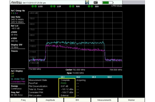
The first measurement for each Uplink Under Test may take approximately 55 seconds to acquire data, synchronize the downlink carrier or carriers to the individual uplink carrier under test, and perform the measurement. See Figure: PIM Over CPRI Data Acquisition.
Trace 3 (in blue) is the latest uplink where testing has completed, and the corresponding measurement results are highlighted with a yellow border. Trace 4 (purple) is the Correlated PIM. Trace 1 and Trace 2 are always off during PIM over CPRI testing.
PIM Over CPRI Measurement Display – UL1 Pass
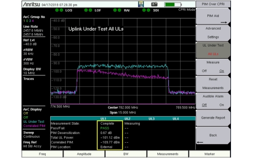
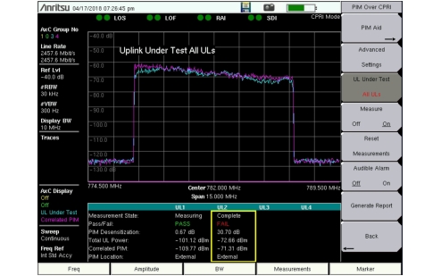
If the Uplink Under Test setting has been configured to cycle through all uplinks, the next uplink to be tested will display as Trace 3 when measurements are completed, and the yellow highlight border in the results table will shift to the appropriate UL number.
PIM Over CPRI Measurement Display – UL2 Fail
To stop the measurement and view the most recent results without the data continually updating, press the Measure key to turn it off. Data for each Uplink Under Test will be re‑acquired and measurements will restart with the current configuration settings when you press Measure On.
Results Table
The results table is empty if you have not yet run PIM over CPRI measurements or you have performed a reset (refer to Reset Measurements). The table will populate with data as measurement completes for each Uplink Under Test. The most recent uplink to complete measurement is highlighted with a yellow border.
Data from previous measurements remain in the results table until they are updated with new measurements or cleared with the Reset Measurements key.
Measurement State
This field indicates the current stage in the uplink’s PIM over CPRI measurement cycle.
• Acquiring – The PIM over CPRI engine is acquiring data and synchronizing the downlinks and uplinks.
• Measuring – PIM over CPRI measurement is being performed on the uplink.
• Complete – Measurement has completed for the uplink and results are displayed in the table.
• Switching UL – The PIM over CPRI engine is finishing the operation currently in progress before starting acquisition or measurement on the uplink newly selected with the UL Under Test menu key.
• Idle – The measurement is running but cannot complete, possibly due to error conditions like insufficient transmit power, or incorrect configuration settings such as AxC group or radio manufacturer. Verify the current settings in the PIM Aid window and make changes as necessary, then press Save and Measure.
• CPRI FAIL – An error occurred on the CPRI link, as indicated by any of the SFP port connection status dots at the top of the display being red or gray, and not green. In the event of a CPRI link failure, the measurement will turn off and must be manually restarted. The new measurement will start with a new acquisition cycle.
Pass/Fail
The measurement Pass/Fail status is based on the acceptable noise floor degradation level specified as the PIM Desensitization Limit configuration setting.
PIM Desensitization
This is the calculated rise in noise floor level that can be attributed to PIM on the uplink contributed by the downlinks being analyzed.
Total UL Power
This is the measured uplink signal strength. The displayed value can be converted from dBm to dBFS and back via the Advanced Settings dialog (see Figure: PIM Over CPRI Advanced Settings).
Correlated PIM
This is the expected PIM contribution from all downlinks that is found to correlate with the Uplink Under Test.
PIM Location
This field indicates the location of the PIM source, internal or external.
Reset Measurements
Pressing the Reset Measurements key under the PIM Over CPRI menu will stop the current measurements if a test is running, and clear all uplink data from the results table. The configuration settings that were last saved will remain in effect.