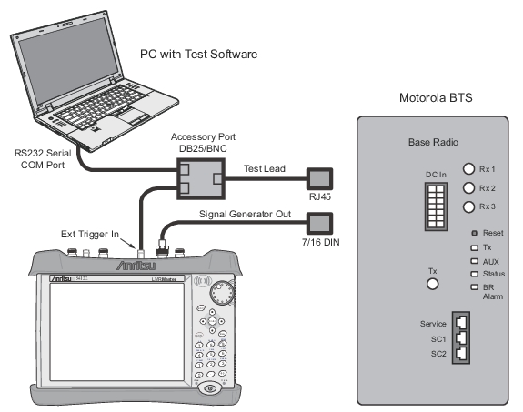
A test PC with HyperTerminal (or similar) is required for this test (Man-Machine Interface (MMI) commands are used to control the BTS using this connection). A special BTS Test/Service Cable (“Service Connector Box”, available from the BTS manufacturer) is used for connecting a PC (RS232 connector) to the Base Radio (RJ45 connector on a service port) and to the S412E test equipment (External Trigger and External Reference BNC connectors). The cable has additional functionality for measuring receiver sensitivity and it is necessary to use the sync pulses from the base radio for the test set timing/synchronization.
Note
The LMR Master S412E supports Motorola MTS and Motorola EBTS Tx patterns. The setup pictured below is for a Motorola MTS base station. Your particular test configuration may be different. Refer to your Motorola Base Station documentation.
Motorola MTS Base Station Setup
1. Connect one end of the service cable to the service computer (RS232 port).
2. Connect the other end of the service cable to the base radio front panel Service access port (RJ45 port).
3. Disconnect the existing cables from the base radio Tx and Rx connectors (or the connector corresponding to the receiver under test).
4. Connect a coaxial test cable to the Tx/Rx antenna port connector (or to the connector corresponding to the receiver under test: Rx 1, Rx 2, Rx 3).
5. Connect the other end of the coaxial test cable to the RF output on a S412E TETRA “Signal Generator Out” (N-female). The S412E should be powered on in a TETRA Analyzer mode and warmed-up according to the operation manual.
6. Connect the Trigger Output connector on the service port cable to the “External Trigger In” on the S412E.
7. Switch on the power of the base radio and enter the test application mode. On the test PC, start the BTS Service Software application, select the proper MTS type and log on (refer to the BTS Service Manual for more details and MMI commands).
S412E Setup
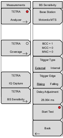
8. On the S412E, set up TETRA Base Station Receiver Sensitivity Mode:
Measurement -> TETRA BS Sensitivity -> Base Station = Motorola MTS or EBTS
The TCH/7.2 Test Pattern ECC will be set with the following: BCC = 1; MCC = 0; MNC = 0.
• Motorola MTS: Trigger Type = External Trigger Edge = Rising Delay Adjustment = 28.064 ms
• Motorola EBTS: Trigger Type = External Trigger Edge = Falling Delay Adjustment = 85.113 ms
9. Set the S412E TETRA signal generator to the receive frequency of the base radio under test:
Frequency -> Tx Freq
All receivers within a single base radio have the same receive frequency.
10. Set the S412E TETRA signal generator to generate the test signal at an output level of –117.5 dBm (or according to particular test requirements):
Amplitude -> Tx Output Lvl.
Use Tx Power Offset menu to compensate losses due to the test cable and adapters in use.
12. WAIT for the “Start Test” button to change to “Stop Test” – this lets you know that the signal generator has synchronized to the BS frame structure and is playing the TCH/7.2 signal.
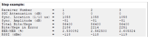
13. Type the corresponding MMI command (refer to the BTS Service Manual for more details) on a service computer test application to analyze the received RF signal quality of the base radio.
14. A performance report is returned including Received Signal Strengths Indicator (RSSI) for each receive path and bit error rate (BER). Verify that these parameters are within specification.
15. Record the results in a test results sheet.
16. Stop the test on the S412E:
Measurement -> TETRA BS Sensitivity -> Stop Test.
17. Repeat Step 11 through Step 15 for all receiver branches.