The LMR Master can analyze the modulation quality and receiver sensitivity of a DMR repeater without needing to remove the repeater from service or to enable a special test mode.
Note
This example procedure illustrates one approach to making a repeater receiver sensitivity measurement. Different configurations may be used depending on accepted test procedures. Refer to High Power Input Protection for an alternate connection method, especially if a direct connection to the repeater RF output is necessary.
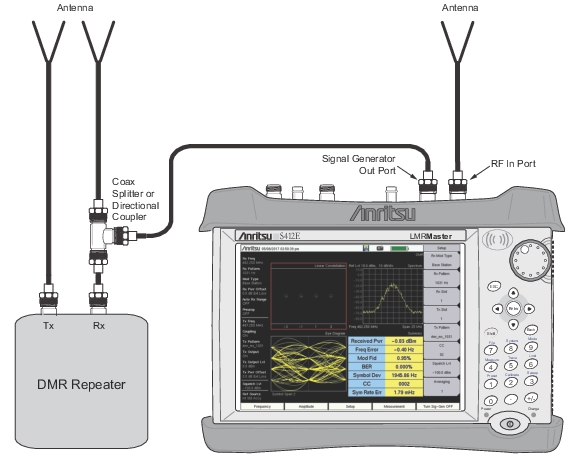
• Connect the DMR repeater Rx port to the S412E Signal Generator Out port and to an antenna via a splitter or directional coupler.
DMR Repeater Sensitivity Measurement Setup Example
2. From the S412E Frequency menu, set the following:
• Rx Freq: DMR repeater transmit frequency
• Tx Freq: DMR repeater receive frequency
• Rx/Tx Coupling: Off
• Coupling Offset: 0 Hz
• Span: 25 kHz
3. From the S412E Amplitude menu, set the following:
• Ref Level: Greater than expected receive signal level
• Scale: 10 dB/div
• Rx Power Offset: 0 dB External Loss
• Auto Rx Range: On
• Tx Power Offset: 3 dB External Loss for splitter (add any additional cable loss)
• Tx Output Level: –60 dBm (initial setting)
4. From the S412E Setup menu, set the following:
• Rx Mod Type: Base Station
• Rx Pattern: 1031 Hz
• RX and Tx Slot: Desired time slot to be measured
• Tx Pattern: dmr_ms_1031
5. Turn the S412E Signal Generator On.
6. Toggle CC to the desired CC for testing. Toggling the CC field is used to send out a “wake-up” signal to the repeater.
7. On a DMR mobile station, listen for a tone. This indicates that the repeater is receiving and retransmitting the test signal from the LMR Master.
8. To determine if the repeater meets the sensitivity level, adjust the LMR Master signal generator output level (Amplitude -> Tx Output Lvl) to the specified sensitivity level.