To obtain accurate results, compensate for any external attenuation or gain by using the Rx Power Offset or Tx Power offset submenus under the Amplitude main menu key. In power offset mode, the compensation factor is in dB. (External attenuation can be created by using an external cable or an external high power attenuator.)
Press the Rx Power Offset or Tx Power Offset submenu key and use the keypad, the arrow keys, or the rotary knob to enter the desired offset value. When using the rotary knob, the value changes in increments of 0.1 dB. Using the Left/Right arrow keys changes the value in 10 % increments of the value shown on the Scale submenu key. When using the Up/Down arrow keys, the value changes in the increment shown on the Scale submenu key. When using the keypad, enter the new value then press Enter or the dB submenu key to set the value. The power offsets for Tx and Rx are displayed in the instrument settings summary column on the left side of the measurement display.
Select the Measurement Types
Analyzer Measurements
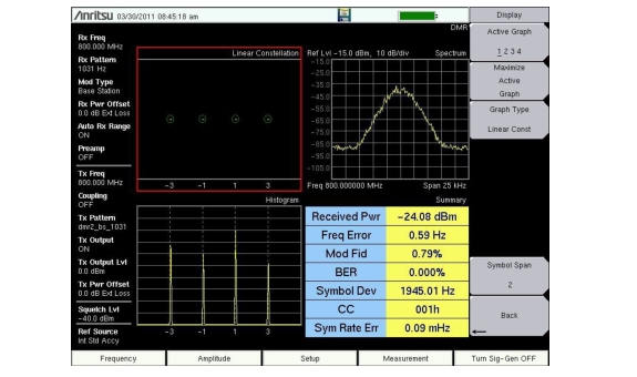
1. Press the Measurement main menu key, then press the P25 Analyzer, P25p2 Analyzer, NXDN Analyzer, dPMR Analyzer,DMR Analyzer,PTC-ITCR Analyzer, PTC-ACSES Analyzer, or the TETRA Analyzer submenu key. Press Graph Type to set the displayed graph types (Figure: Analyzer Measurements (Active Graph has the Red Outline)).
2. Select the graph to change with the Active Graph submenu key or the touchscreen. Change the graph with the Graph Type submenu key.
Analyzer Measurements (Active Graph has the Red Outline)
Control Channel Measurement (not available in dPMR, PTC-ITCR and PTC-ACSES, or TETRA modes)
1. Press the Setup main menu and set the Rx Pattern to Ctrl Channel or Voice.
2. Press the Measurement main menu key, then press the P25 Control, P25p2 Control, NXDN Control or DMR Control submenu key twice.
3. To save control channel data for additional analysis, insert a formatted USB memory device into the LMR Master and turn Log DataOn.
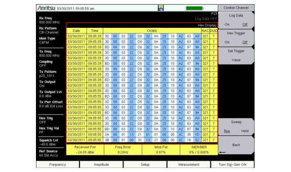
4. Set the Hex Trigger, Sweep and Set Trigger Value (Figure: Control Channel Measurement). The Hex Trigger menu and Hex Trigger Value menu are used to find a specific opcode in the Control Channel data. To set the hex trigger value, press the Set Trigger Value menu. An on screen keyboard will display and with the numbers 0 to 9 and the letters A to F. Enter the two character hex value to search for. After entering the value, press Enter to set the trigger value. Press Esc to cancel entry or changing the current hex value.
Setting Hex Trigger to On will set the Sweep function to Hold when the hex trigger value is found in the first octet of a packet. The octet row with the found trigger value will be displayed in the middle of the table. If Log Data is set to On, all of the data on the screen is saved and Log Data is set to Off. When Sweep is set back to Run, the unit will continue to collect data and stop on the next instance of the hex trigger value. To continue to capture data to the USB memory device, set Log Data back to On before setting Sweep to Run mode.
Control Channel Measurement
Note
This measurement is captured on an external USB memory device. The captured data file can not be recalled and displayed on the instrument screen.
Coverage Measurements
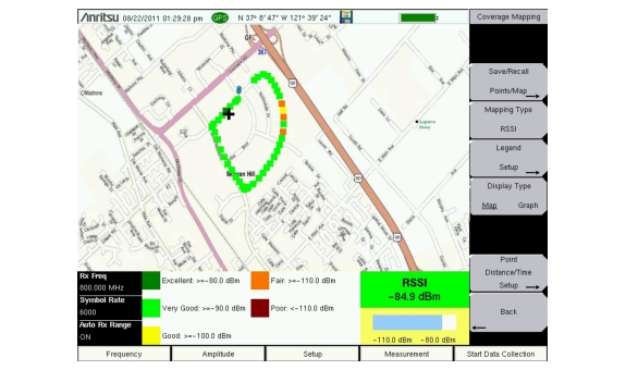
1. Press the Measurement main menu key, then press the P25 Coverage, P25p2 Coverage, NXDN Coverage, dPMR Coverage, DMR Coverage, PTC-ITCR Coverage, PTC-ACSES Coverage, or TETRA Coverage submenu key twice (Figure: Coverage Measurements).
2. Refer to the Land Mobile Radio Measurement Guide listed in Measurement Guides for details on creating a map and coverage mapping.
Coverage Measurements
Bit Capture Measurement (not available in dPMR, PTC-ITCR and PTC-ACSES, or TETRA modes)
1. Press the Setup main menu and set the Rx Pattern to Voice.
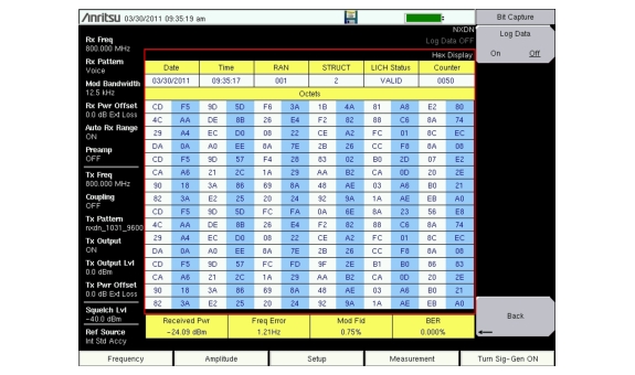
2. Press the Measurement main menu key, then press the P25 Bit Capture, P25p2 Bit Capture, NXDN Bit Capture or DMR Bit Capture submenu key.
3. To save bit capture data for additional analysis, insert a formatted USB memory device into the LMR Master and turn Log Data On. (Figure: Bit Capture Measurement).
Bit Capture Measurement
IQ Capture Measurement
1. Insert a formatted USB memory device in the USB port of the LMR Master.
2. Press the Measurement main menu key, then press the P25 IQ Capture, P25p2 IQ Capture, NXDN IQ Capture, dPMR IQ Capture, DMR IQ Capture, PTC-ITCR, PTC-ACSES, IQ Capture, or TETRA IQ Capture submenu key.
3. After a few seconds the LMR Master will display the message “IQ Capture Complete”.
4. The IQ data is stored on the USB memory device under the /usr folder in a date stamped folder. The file will be IQ_CAPTUREyearmonthdaytime.p25 (or .p252, .nxdn, .dpmr, .dmr2, .ptc, .acses, or .tetra).
Note
These measurements are captured on an external USB memory device. The captured data file can not be recalled and displayed on the instrument screen.