 | |
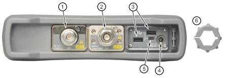
1 | RF Out/Reflect In port (Type N, Female) – 50 ohm impedance; depending on hardware revision, maximum input is +42 dBm or +23 dBm at ±50 VDC. Check connector label. Torque to 12 in· lbs. This connector port for Cable and Antenna measurements. Before making measurements, connect a phase-stable test port cable to the RF Out/Reflect In port connector and perform a calibration using the internal InstaCal (#2) or an external OSL. Refer to Calibration Symbols and Calibration. |
2 | InstaCal/Power Meter port (Type N, Male) – 50 ohm impedance; maximum input is +27 dBm, ±45 VDC. Torque to 12 in · lbs. This port supports dual functions. It can be used for performing user calibrations in both Cable & Antenna Analyzer modes, or it can be used as a power meter in Power Meter mode. It is not capable of performing both functions simultaneously. |
3 | USB Interface – Type A (version 2.0) The Site Master has two Type A USB 2.0 connectors that accept USB Flash Memory devices for storing or transferring measurements, setups, and screen shots. Certain USB peripheral devices such as a USB GPS module, USB mouse, or USB keyboard may also be supported. |
4 | External Power The external power connector is used to power the unit and for battery charging. Input is 11 VDC to 14 VDC at up to 3.0 A. When using the AC-DC Adapter, always use a grounded three-wire power cable that is connected to a three-wire power line outlet. Failure to use properly grounded electrical equipment may result in severe or potentially fatal injury. |
5 | USB Interface – Type Mini-B (version 2.0) The USB 2.0 Mini-B connector can be used to connect the Site Master directly to a PC. The first time the Site Master is connected to a PC, the normal USB device detection by the computer operating system will take place. When connecting the Site Master to a local area network, use an Anritsu-approved USB-to-RJ45 adapter. The instrument will obtain an IP address via DHCP, or a static IP address can be set by the user. Refer to Status Menu for information about obtaining the IP address of the instrument. |
6 | Removable Torque Multiplier Nut Used to assist in firmly securing RF cable(s) to the InstaCal/Power Meter (4) port. |