Markers can be applied to active or recalled measurements. The instrument supports eight markers. Marker information is stored in measurement and setup files and is displayed when either file type is recalled. Pressing the Marker main menu key will bring up the marker functions.
Overview of Markers:
• Frequency measurements (Return Loss, Cable Loss, and VSWR) have common markers. Distance measurements (DTF Return Loss and DTF VSWR) also have common markers.
• Press and hold on a marker to select and display the frequency/ distance and amplitude information, drag a marker to move it.
• The selected marker displays a red line and is the highlighted row in the marker table. Select a marker to edit with the touchscreen or the Select Marker button.
• Selected markers can be quickly dragged to a new location using the touchscreen or moved by double-tapping on the display.
• Markers can be selected (and moved) outside of the Marker menu. Press and hold on a marker (thin green line) for a few seconds to make it active and ready for moving. After a few seconds the instrument will automatically deselect the marker.
• Markers set beyond the current frequency or distance range are displayed at either the left or right of the graticule.
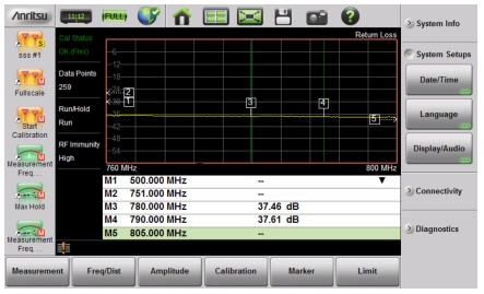
• If the frequency (F1 or F2) or distance (D1 and D2) parameters are moved inside a current marker location, the out range (---> or <----) indicator is displayed and marker values in the Table are blanked (--). See Figure: Markers 1, 2, and 5 are Out of Range for an example of markers beyond the current span.
• Markers beyond the current span cannot be edited.
• Marker locations and type are stored after the marker is turned off.
• Marker Preset restores the markers to their default state. All markers are turned off except for Marker 1 which is set to the middle of the sweep. Previous marker information is not saved.
Markers 1, 2, and 5 are Out of Range
Select, Activate, and Place a Marker / Delta Marker
1. Press the Marker main menu key. One of the markers is automatically selected. Select a different marker with the Select(1-8) button. Press one of the Marker buttons to turn the marker on and make the marker active. The active marker is red.
2. Press the Edit menu and use the Up/Down arrow keys, the keypad, the rotary knob, or the touchscreen to move the marker.
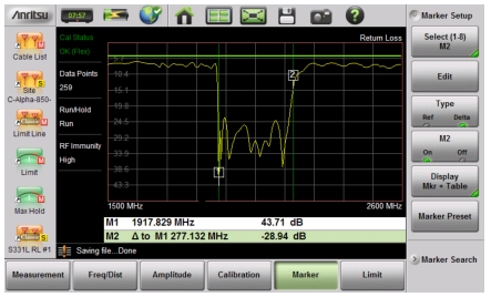
3. Markers 2 through 8 can be set as deltas to a reference marker. Use the Type key to set the marker type as Reference or Delta marker. Figure: Delta Marker 2 and Marker Table illustrates using a delta marker to estimate the passband of a filter.
Marker Table
The Marker Table displays below the sweep window. The table is automatically sized to display all markers that are turned on. The table displays marker frequency/distance, amplitude and delta information for delta markers. To display the marker table:
1. Press the Marker main menu key, then Display. Select Mkr + Table.
Delta Marker 2 and Marker Table
Marker Search
All the cable & antenna measurements include markers that will find trace peak and or trace valley automatically.
1. Press the Marker main menu key then Marker Setup. Select the marker to use for peak or valley.
2. Press Marker Search.
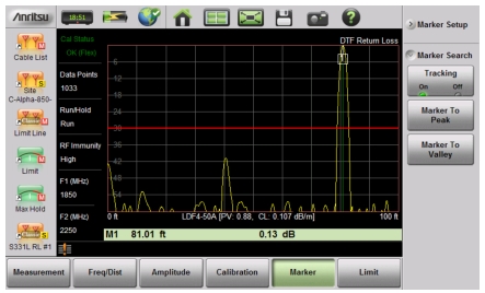
3. Press Marker To Peak to set the marker to the peak of the measurement or Marker To Valley to set the marker to valley of the measurement.
Marker Search, Marker 1 Set to Peak
Peak Between Markers
Another marker search option is to select the peak or valley between two Markers instead of the entire displayed frequency or distance span.
Markers 5 and 7 can be used to find the peak or valley between Marker 1 and Marker 2.
Markers 6 and 8 can be used to find the peak or valley between Marker 3 and Marker 4.
3. Press Marker Search and select Peak between M1 & M2 or Valley Between M1 & M2. Marker 5 will now move to the peak or valley between M1 and M2.
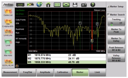
4. In Figure: Bounded Marker Search, Marker 5 moved to the valley bounded by M1 and M2 instead of the lowest point (48 dB) to the left of Marker 1. The valley search would also work if M1 and M2 were set and then turned off.
Bounded Marker Search
Note
Searching for peaks or valleys turns on any required markers and place them in the default locations.
Tracking Markers
A tracking marker is set to a peak or to a valley. As the peak (or valley) varies in the measurement trace, the tracking marker stays at the peak (or valley).
Any marker can be set for tracking from the Marker Search menu. When set to Tracking, the marker number is displayed inside a triangle rather than a rectangle. For a Tracking marker set for Marker To Peak, the apex of the triangle points upward. For a Tracking marker set for Marker To Valley, the apex of the triangle points downward.
The markers that can be set for Peak Between can also be Tracking markers that are bounded by M1 and M2 or by M3 and M4.
Tracking markers can be especially helpful for specific measurements, such as tuning and testing filters or antennas.
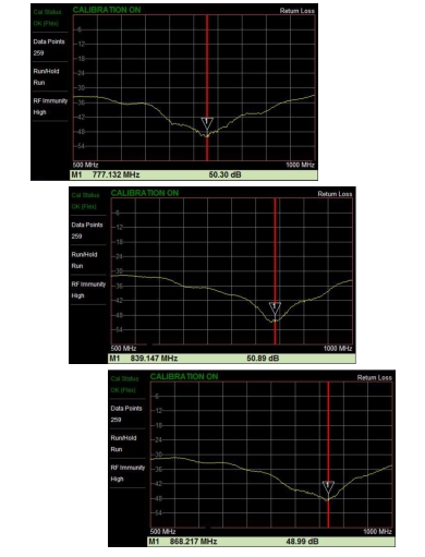
In Figure: Tracking Marker Set to Valley, Marker M1 is set for Tracking a Valley. The three images show how the marker remains at the valley as the measurement trace changes.
Tracking Marker Set to Valley
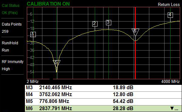
In Figure: Tracking a Valley Between Markers, Marker M5 is set for Tracking a Valley between markers M1 and M2. Marker M6 is Tracking a Valley between markers M3 and M4. The table of markers (below the sweep window in Figure: Tracking a Valley Between Markers) shows only 4 markers, but the table can be expanded or reduced by tapping on the table.