Attaching the MA24105A inline peak power sensor adds additional menus and submenus required for making the following in-line measurements:
• Forward Measurements: Average Power, Crest Factor, Peak Envelope Power (PEP), Burst Average Power, and CCDF.
• Reverse Measurements: Average Power, Reflection Coefficient, Return Loss, and VSWR.
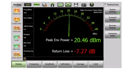
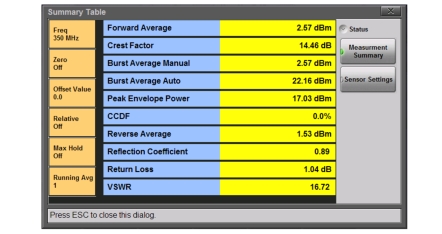
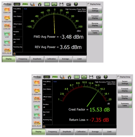
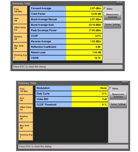
In the default view the analog meter displays the forward measurements. The reverse measurements are displayed below the numerical display of the forward measurements (Figure: Power Meter View). To view all of the forward and reverse measurements in table format, use the Summary Table display (Figure: Summary Table View).
Power Meter View
Summary Table View
In-Line Sensor Setup
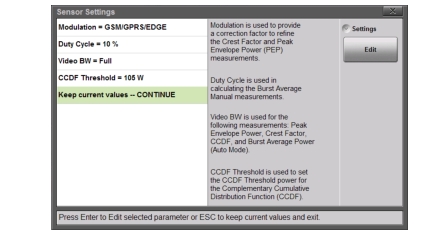
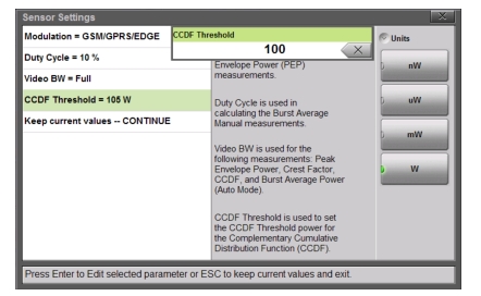
The Sensor Settings submenu under the Display main menu adjusts the in-line sensor parameters (Figure: Sensor Settings). The on screen instructions provide information for each parameter. To change a parameter, select it with the Up/Down arrows or the touchscreen and press Edit.
Note
Several sensor settings are only appropriate for specific measurements. Refer to the on screen information in the Sensor Settings dialog for additional information.
Sensor Settings
Modulation
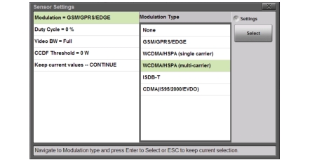
In the Sensor Settings dialog, highlight the Modulation = ... row and press Edit. Use the Up/Down keys, rotary knob or touchscreen to highlight the desired modulation type, and then press Select.
Sensor Settings
The selection of a specific modulation type provides a correction factor to refine the PEP calculation.
Duty Cycle
Sets the duty cycle used for averaging when the forward measurement is set to Burst Average Manual. Select a value from 0% to 100%. In the Sensor Settings dialog, highlight the Duty Cycle = ... row and press Edit. Use the Up/Down keys, rotary knob or key pad to set the duty cycle and then press Enter.
Video Bandwidth
Sets the Video Bandwidth span used in several forward measurements. In the Sensor Settings dialog, highlight the Video BW = ... row and press Edit. Use the Up/Down keys, rotary knob or touchscreen to highlight the desired View BW and then press Select.
CCDF Threshold
Sets the power threshold value used in the Complementary Cumulative Distribution Function (CCDF) forward measurement. CCDF describes the probability that the signal power is greater than the user-define threshold value. In the Sensor Settings dialog, highlight the CCDF Threshold ... row and press Edit. Set the desired value and press one of the units of measure buttons to complete.
CCDF Threshold
Displayed Measurements
Select the forward and reverse measurements to display in the graph area (the analog graph always shows the forward measurement). Select Forward Display and/or Reverse Display under the Display main menu and choose a measurement. See Figure: Sensor Settings for examples of measurement combinations. Refer to Forward Menu and Reverse Menu for additional information.
Forward and Reverse Measurement Combinations
Summary View
The Summary Table button under the Display main menu provides a summary of Site Master instrument settings, DUT forward and reverse measurements, and sensor settings (Figure: Summary Table).