Remote programming and operation of the MS20xxC is accessed via the Ethernet or USB interface. The following paragraphs provide information about the interface connections, cable requirements, and setup for remote operation.
Ethernet Interface Connection and Setup
The MS20xxC uses Ethernet to communicate remotely with a controller. Most MS20xxC functions (except power On/Off) can be controlled via an Ethernet connection to a PC that is connected directly (with an Ethernet cross‑over cable) or through a network. The instrument software supports the TCP/IP network protocol.
Ethernet networking uses a bus or star topology in which all of the interfacing devices are connected to a central cable called the bus, or are connected to a hub. Ethernet uses the CSMA/CD access method to handle simultaneous transmissions over the bus. CSMA/CD stands for Carrier Sense Multiple Access/Collision Detection. This standard enables network devices to detect simultaneous data channel usage (called a collision) and provides for a contention protocol. When a network device detects a collision, the CSMA/CD standard dictates that the data is retransmitted after waiting a random amount of time. If a second collision is detected, then the data is again retransmitted after waiting twice as long. This is known as exponential back off.
The TCP/IP setup requires the following:
• IP Address: Every computer/electronic device in a TCP/IP network requires an IP address. An IP address has four numbers (each between 0 and 255) separated by periods. For example: 128.111.122.42 is a valid IP address.
• Subnet Mask: The subnet mask distinguishes the portion of the IP address that is the network ID from the portion that is the station ID. The subnet mask 255.255.0.0, when applied to the IP address given above, would identify the network ID as 128.111 and the station ID as 122.42. All stations in the same local area network should have the same network ID, but different station IDs.
• Default Gateway: A TCP/IP network can have a gateway to communicate beyond the LAN that is identified by the network ID. A gateway is a computer or electronic device that is connected to two different networks and can move TCP/IP data from one network to the other. A single LAN that is not connected to other LANs requires a default gateway setting of 0.0.0.0. If you have a gateway, then the default gateway would be set to the appropriate value of your gateway.
• Ethernet Address: An Ethernet address (also known as a MAC address) is a unique 48‑bit value that identifies a network interface card to the rest of the network. Every network card has a unique ethernet address permanently stored into its memory.
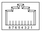
Interface between the MS20xxC and other devices on the network is via a category‑five (CAT‑5) interface cable that is connected to a network. This cable uses 4 twisted pairs of insulated copper wires that are terminated at an RJ45 connector. CAT‑5 cabling is capable of supporting frequencies up to 100 MHz and data transfer speeds up to 1 Gbps, which accommodates 1000Base‑T, 100Base‑T, and 10Base‑T networks. CAT‑5 cables are based on the EIA/TIA 568 Commercial Building Telecommunications Wiring Standard developed by the Electronics Industries Association. A pinout diagram is shown in Table: 8‑pin Ethernet RJ45 Connector Pinout Diagram.
8‑pin Ethernet RJ45 Connector Pinout Diagram
Pin
Name
Description
Wire Color
1
TX +
Transmit data (> + 3 volts)
White/Orange
2
TX –
Transmit data (< – 3 volts)
Orange
3
RX +
Receive data (> + 3 volts)
White/Green
4
—
Not used (common mode termination)
Blue
5
—
Not used (common mode termination)
White/Blue
6
RX –
Receive data (< – 3 volts)
Green
7
—
Not used (common mode termination)
White/Brown
8
—
Not used (common mode termination)
Brown
Connectivity
TCP/IP connectivity requires setting up the parameters that are described at the beginning of this section. The following is a brief overview of how to set up a general LAN connection on the MS20xxC.
Note
You may need to consult your network documentation or network administrator for assistance in configuring your network setup.
MS20xxC LAN Connections
The RJ‑45 connector is used to connect the MS20xxC to a local area network (LAN). Integrated into this connector are two LEDs. The amber LED (Light Emitting Diode) indicates the speed of the LAN connection (ON for 10 Mb/s and OFF for 100 Mb/s), and the green LED flashes to show that LAN traffic is present. The instrument IP address is set by pressing the Shift key, then the System (8) key, then the System Options soft key, and then the Ethernet Config soft key. The instrument IP address can be set automatically by using DHCP, or can be set manually by entering the desired IP address, gateway address, and subnet mask.
Note
An active Ethernet cable must be connected to the MS20xxC before it is turned ON in order to enable the Ethernet port for DHCP or for a static IP address.
Depending upon local conditions, the port may remain enabled when changing from DHCP to static IP address, when changing from static IP address to DHCP, or when temporarily disconnecting the Ethernet cable.
If the port becomes disabled, ensure that an active Ethernet cable is attached to the MS20xxC, and then cycle the power OFF and back ON.
Dynamic Host Configuration Protocol (DHCP) is an Internet protocol that automates the process of setting IP addresses for devices that use TCP/IP, and is the most common method of configuring a device for network use. To determine if a network is set up for DHCP, connect the MS20xxC to the network and select DHCP protocol in the Ethernet Config menu.
Power cycle the MS20xxC. If the network is set up for DHCP, then the assigned IP address should be displayed briefly after the power‑up sequence.
To display the IP address of the instrument, press the Shift key, then the System (8) key, then the System Options soft key, and then the Ethernet Config soft key.
USB Interface Connection and Setup
Note
For proper detection, Master Software Tools must be installed on the PC prior to connecting to the MS20xxC using the USB port. Master Software Tools provides the installation tools to install the USB and VISA drivers.
The Universal Serial Bus (USB) architecture is a high‑performance networking standard that is considered “plug and play” compatible. The USB driver software is automatically detected and configured by the operating system of the devices that are connected to the bus. The MS20xxC conforms to the USB 2.0 standard and is a USB “full‑speed” device that supports data rates of up to 10 Mbps with the following restrictions:
• One USB network can support up to 127 devices
• The maximum length of USB cables between active devices is 5 meters (for USB 2.0) and 3 meters (for USB 1.0)
To run the following example, you must have NI‑VISA 2.5 or later installed on the controller PC, and you must select the VISA library (visa32.dll) as a reference in a Visual Basic project. For remote USB control, the controlling PC needs to have a version of VISA installed that supports USBTMC (USB Test and Measurement Class) devices.
1. Turn On power to the MS20xxC and controller PC and wait for the systems to power up completely.
2. Connect the USB cable mini‑B connector to the MS20xxC.
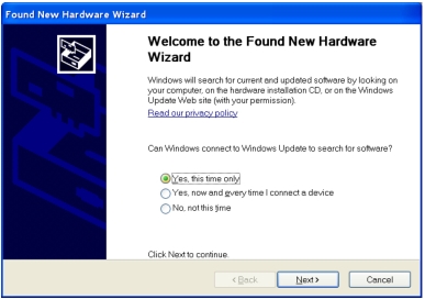
3. Connect the USB cable A connector to the controller PC USB host port. The controller PC should indicate “New Hardware Found” if the combination of USB VID/PID/Serial Number has never been connected to this controller PC.
USB Found New Hardware Wizard
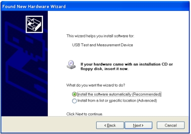
4. Select to allow the Wizard to search for and install the USB software automatically.
USB Found New Hardware Wizard
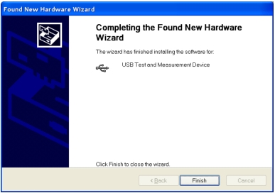
5. After the software is installed, close the Wizard by clicking Finish.
USB Found New Hardware Wizard
USB Interface, Type Mini‑B
The USB 2.0 Mini‑B device connector can be used to connect the MS20xxC directly to a PC. The first time that the MS20xxC is connected to a PC, the normal USB device detection is performed by the computer operating system. The driver is installed when Master Software Tools is installed (available from http://www.anritsu.com).