When cables are installed in the field, one end of the cable is often too far away to allow you to conduct a full 2‑port measurement. The 1‑port measurement is an ideal technique for this situation.
Setup Considerations
To conduct a 1-port cable measurement, the first step is to set the frequency range of interest and the desired number of points in the sweep. Then set the test port power to high and perform a full S11 Open-Short-Load (OSL) calibration by using the appropriate connector type. Connect the easily accessible side of the cable to Port 1 of the VNA Master, and connect a short or an open to the far end of the cable. Finally, set up the instrument to display the measurement results in the desired format.
Measurement Readout and Interpretation
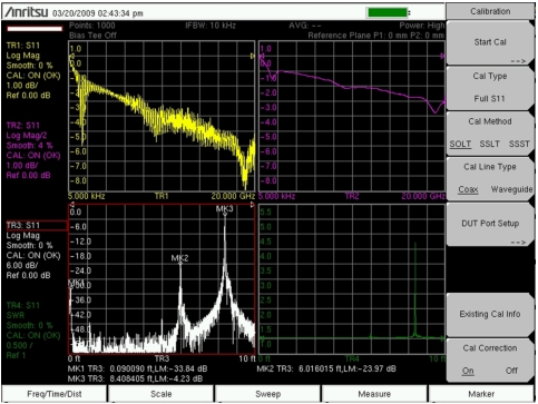
The screen‑captured measurement that is shown in Figure: Four‑Trace S11 Display uses a four‑trace display to show S11, a smoothed version of S11/2, a distance‑to‑fault (DTF) measurement using return loss, and another distance‑to‑fault measurement using SWR. Note that these four measurements are displayed in Quad format as Trace 1 (upper left quadrant), Trace 2 (upper right quadrant), Trace 3 (lower left quadrant), and Trace 4 (lower right quadrant). For an explanation of trace format versus the number of traces that are displayed, refer to section Trace Format Menu. The screen‑captured measurements that are shown in this measurement guide are examples and may not match any display on your instrument.
Four‑Trace S11 Display
SWR as a good tool for identifying major discontinuities, and Return Loss is better for identifying minor discontinuities.
To calculate cable loss, the far end of the cable is shorted, and the resulting S11 return loss measurement is divided by two (S11/2) to compensate for the round‑trip loss of the cable. Smoothing can be applied to remove any ripples in the 1-port cable loss response. The ripples that are seen in TR1 (Trace 1) are caused by the phase interactions of the large reflection at the short at the end of the cable and the small reflection of the connector at the near end of the cable. In normal cable use, the far end of the cable is terminated with some device, which would eliminate the large reflection in the image with the short. To accurately measure the loss in the cable, however, the signal must be fully reflected from the far end of the cable, which is why a short or an open is used. The resulting undesired ripple can be removed by using smoothing. A smoothing setting of 2 % to 5 % is usually sufficient to remove the ripples.
Note
If you apply smoothing when the sweep has more than 2000 points, the smoothing may slow the sweep time of the trace and the responsiveness of the instrument. This slowing can be significant, and it increases as the number of sweep points is increased.
This particular cable shows (at MK2) unwanted dips (troughs) in the insertion loss frequency sweep. The optional time domain or distance‑to‑fault measurement can reveal potential causes for the poor frequency response of the cable.
In this example, a loose connector that is located 6 feet down the cable was causing a sizable degradation in performance. Marker 1 shows the mismatch of the near end cable connector, Marker 2 highlights the loose connection, and Marker 3 shows the full reflection of the short at the end of the cable. (MK3 is not a full 0 dB reflection, but somewhat less. This can be attributed to the loss of the cable and the previous smaller reflections at MK1 and MK2, which both contribute to the reduced magnitude of the reflected signal at the far‑end short.)
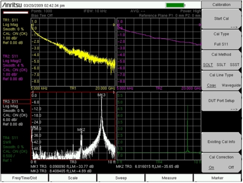
After tightening the connector, the insertion loss becomes well behaved, and the mismatch from the connector is significantly reduced, as shown in Figure: Improved Trace with Connector Tightened.
Improved Trace with Connector Tightened
The 1‑port measurement approach is useful for deployed cables, but does have a practical limitation. Uncertainties become large as the round‑trip cable loss exceeds 15 dB. This threshold is easy to surpass for long cable lengths or for high operating frequencies. For longer cables and higher frequencies, a 2‑port measurement is required for improved accuracy.