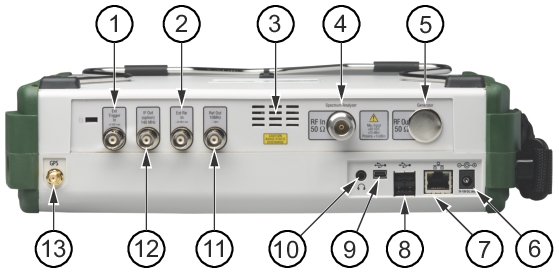
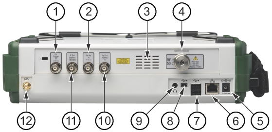
Spectrum Analyzer RF In Port, Ruggedized Type K Connector
5.
External Power Connector
6.
LAN Connection
7.
USB Interface, Type A
8.
USB Interface, Type Mini‑B
9.
Headset Jack
10.
Reference Out Connector, 10 MHz
11.
IF Out Connector, 140 MHz (Option 89)
12.
GPS Antenna Connector
Ext Trigger In
A TTL signal that is applied to the External Trigger 50 Ω female BNC input connector causes a single sweep to occur. In the Spectrum Analyzer mode, it is used in zero span, and triggering occurs on the rising edge of the signal. After the sweep is complete, the resultant trace is displayed until the next trigger signal arrives.
Ext Ref In
The External Reference In port is a 50 Ω BNC female connector that provides for input of an external frequency reference. Refer to your technical data sheet for valid frequencies and input levels. To prevent damage to your instrument, do not use pliers or a wrench to tighten the BNC connector or overpower the input.
RF In
Warning
To prevent damage to your instrument, do not use pliers or a plain wrench to tighten the connector. Do not overtighten the connector. Do not overpower the RF Input. Refer to your technical data sheet for valid frequencies and input levels. Typical maximum input is +23 dBm (±50 VDC).
MS2720T‑0709, MS2720T‑0713, MS2720T‑0720
Type N(f), 50 Ω connector. The recommended torque is 12 lbf · in to 15 lbf · in (1.36 N · m to 1.70 N · m).
MS2720T‑0732, MS2720T‑0743
Type K(f), 50 Ω ruggedized connector. The recommended torque is 8 lbf · in (0.9 N · m or 90 N · cm).
Tracking Generator RF Out
This is a 50 Ω Type N female connector (MS2720T‑0809, MS2720T‑0813, MS2720T‑0820). To prevent damage to your instrument, do not use pliers or a plain wrench to tighten the Type‑N connector. The recommended torque is 12 lbf · in to 15 lbf · in (1.36 N · m to 1.70 N · m).
External Power
This is a 2.1 mm by 5.5 mm barrel connector, 12 to 15 VDC, < 5.0 A. The external power connector is used to power the unit and for battery charging. A green blinking LED near the Power button indicates that the instrument battery is being charged by the external charging unit. The indicator is a steady green when the battery is fully charged.
Warning
When using the AC-DC Adapter, always use a three-wire power cable that is connected to a three-wire power line outlet. If power is supplied without grounding the equipment in this manner, the user is at risk of receiving a severe or fatal electric shock.
The RJ‑45 connector is used to connect the Spectrum Master to a local area network or directly to a PC with an Ethernet crossover cable. Integrated into this connector are two LEDs. The amber LED shows the presence of a 10 Mbit/s LAN connection when on, and a 100 Mbit/s LAN connection when off. The green LED flashes to show that LAN traffic is present. For more information on the LAN connection, Ethernet connection, and DHCP, refer to Web Remote Control and LAN and DHCP.
USB Interface – Type A
The Spectrum Master has two Type A USB connectors that accept USB Flash Memory devices for storing measurements, setup data, and screen images.
USB Interface – Type Mini‑B
The 5‑pin mini‑B USB 2.0 interface can be used to connect the Spectrum Master directly to a PC. The first time the MS2720T is connected to a PC, the normal USB device detection by the computer operating system will take place. A Windows driver is installed when Master Software Tools is installed. Drivers are available for versions of the Windows XP operating system and later. During the driver installation process, specify that the installation wizard should search the Master Software Tools directory for the driver.
Note
For proper detection, Master Software Tools should be installed on the PC prior to connecting the Spectrum Master to the USB port.
Headset Jack
The 3‑wire headset jack provides audio output from the built‑in AM/FM/SSB demodulator and from other sounds generated by the instrument. The jack accepts a 3.5 mm 3‑wire miniature phone plug such as those commonly used with cellular telephones.
Ref Out 10 MHz
The External Reference Out port is a 50 Ω BNC female connector that provides 10 MHz at approximately –7 dBm to 0 dBm. To prevent damage to your instrument, do not use pliers or a wrench to tighten the BNC connector.
IF Out 140 MHz (Option 89)
This 50 Ω BNC female connector is for Zero Span 140 MHz IF Output with Option 89. To prevent damage to your instrument, do not use pliers or a wrench to tighten the BNC connector.
GPS Antenna Connector (Option 31)
The GPS antenna connection on the Spectrum Master is type SMA-female. GPS function is described in GPS (Option 31).