Before testing for PIM, ensure that line sweeping has been performed so that you can be confident that the insertion loss and return loss data are at acceptable levels. These results ensure that the PIM test signals actually reach the components at the highest possible signal level, and therefore offer the most accurate indication of true PIM performance.
The basic test for PIM at your test site is a PIM versus Time measurement. Anritsu recommends that you set up the PIM Master for a PIM versus Time measurement and then perform a Noise Floor measurement before you begin PIM testing. Refer to PIM versus Time and Noise Floor Measurement for setup and measurement procedures. The Noise Floor test is basically a PIM versus Time measurement with the PIM transmit tones turned off and the PIM Master receiver activated.
If a Noise Floor test reveals external interference that you suspect is from mobile equipment, then you can try shifting carrier F2 to the next guard band frequency and repeating the Noise Floor measurement. This will shift the IM3 frequency and may provide you with a clear IM3 frequency for the PIM versus Time measurement. See Figure: PCS Band PIM Testing.
After the IM3 frequency has been verified to be clear of interference, perform a PIM versus Time measurement to search for any static PIM sources.
If static PIM sources are found that exceed the pass / fail criteria, then use Distance‑to‑PIM (DTP) to locate and eliminate these static PIM sources. If DTP identifies multiple PIM sources, then correct the largest magnitude fault and repeat the DTP measurement. Repeat this process until magnitudes of all reported PIM faults appear acceptable.
Return to PIM vs. Time and perform a dynamic PIM test to verify that all RF connections and components are robust. A dynamic PIM test involves lightly tapping on all RF connections and components in the system while measuring PIM versus Time. If the peak PIM observed during the dynamic test is below the customer's pass/fail threshold, then save the measurement.
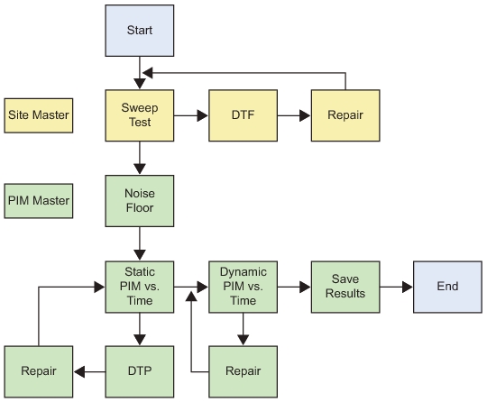
Recommended Testing Procedure
Recommended Testing Procedure Work Flow
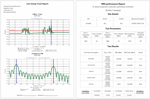
Test Reports
Use Line Sweep Tools (LST) to view and create reports from saved PIM measurements. Line Sweep Tools can generate a standard report showing plots of the measured results. LST can also generate a special PIM report to display PIM versus TIME results in a tabular format.