The Anritsu MW82119A PIM Master is capable of approximately 3.0 hours of continuous operation from a fully charged, field‑replaceable battery (refer to Battery Replacement). The PIM Master can also be operated from a 12 VDC source (which will also simultaneously charge the battery). This can be achieved with either the Anritsu AC Adapter or Automotive 12 Volt Adapter. Both items are included as standard accessories (refer to the list of accessories in the Technical Data Sheet for your specific instrument, as listed in Other Documents).
Caution
When using the Automotive Adapter, always verify that the supply is rated for a minimum of 60 Watts at 12 VDC and that the socket is clear of any dirt or debris. If the adapter plug becomes hot to the touch during operation, then discontinue use immediately.
To turn on the MW82119A PIM Master, press the On/Off button on the front panel (Figure: MW82119A PIM Master Front Panel). The PIM Master takes approximately forty seconds to complete power‑up and to load the application software. At the completion of this process, the instrument is ready to be used.
Note
Anritsu recommends that you turn on your PIM Master and let it warm up for 10 minutes before performing your first calibration. Without warm-up, re-calibration will be required (due to internal temperature change) approximately 30 minutes after the initial, cold calibration.
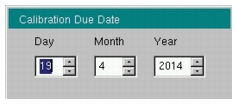
Calibration Due Date
On first use, or if the Calibration Reminder setting is greater than the due date, a menu is displayed requesting that you enter the Calibration Due Date for this instrument. This date is available on the calibration sticker that is provided with the instrument. Enter the correct day, month, and year and then press Enter.
Calibration Due Date
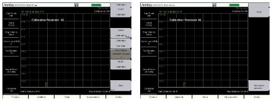
Calibration Reminder
You can set a reminder of the due date by pressing the Days Before Calibration Reminder submenu key and entering a number with the number keypad. Complete the entry by pressing the Enter submenu key or the instrument Enter key.
Days Before Calibration Reminder
Preparing for Measurements
Along with your PIM Master, you need tools and components that are provided in the accessory kit, and you need to set up the instrument for your planned measurements.
Checking Required Tools and Components
The following items are supplied with your PIM Master accessory kit or can be ordered separately as individual components. Consult your Technical Data Sheet for part numbers.
• Test port cable
• Connector Saver (included with instrument, 7/16 DIN(f) to 7/16 DIN(m), 50 Ω adapter)
Note
Install the connector saver on the test port (RF output) of the PIM Master using a torque wrench. The recommended torque is 25 N · m (~18 lbf · ft). This protects the test port from wearing out. Typically, 500 matings is the life of a connector for PIM testing. The connector saver can remain on the PIM Master while inside the soft case or the transit case.
• RF Adapters
• PIM Standard
• Low PIM Termination
• Torque Wrench
• Adjustable Wrench
• Cleaning Kit
Setting Up the PIM Master
With the PIM Master on, check the upper‑right corner of the display screen to verify that the PIM Master is in PIM Analyzer mode, or press Shift and Mode (9) and verify that the PIM Analyzer mode is selected. Press Esc, if necessary, to close the Mode Selector window.
1. If necessary, press the Menu key and then press the PIM Analyzer icon.
2. Before calibrating the PIM Master, set the parameters for all three measurement types. This will eliminate the need for recalibrating due to changing parameters. To set up the parameters for all three measurement modes, perform the following steps.
3. Press the Measurements main menu key and then press the PIM vs. Time submenu key.
4. Press the Freq main menu key, then select the input frequencies for the F1 and F2 carriers, and then select the intermodulation order.
a. Press the Carrier F1 submenu key and set the desired frequency.
b. Press the Carrier F2 submenu key and set the desired frequency.
c. If necessary, press the Intermod Order submenu key until the desired setting is underlined (3rd, 5th, or 7th).
5. Press the Setup main menu key to set the power level and test duration.
6. Press the Measurements main menu key and then press the Distance‑to‑PIM submenu key.
7. Press the Setup main menu key, then the DTP Aid submenu key.
8. On the DTP Parameters screen, use the touch screen to enter or select values for Distance, Data Points, and Cable type (or enter Cable Loss and Propagation Velocity).
9. Press the Measurements main menu key and then press the Swept PIM submenu key.
10. Press the Setup main menu key,
11. Set the Output Power level and Test Duration.
12. Press the Freq main menu key
13. Set the Step Size and Intermod Order.
14. Visually inspect all RF connectors on the test instrument, test lead, PIM standard, and Low PIM termination. Clean connections each day prior to first use.
This measurement tracks instantaneous PIM and also records Peak PIM levels throughout a fixed frequency PIM test. It is useful for dynamic PIM tests and provides a visual indication of the stability of the system under test.
Noise Floor
This measurement tests for Rx interferers before making a PIM versus Time measurement. In this measurement, Tx power is Off. This allows you to check for external interference at the IM frequency being measured.
The IM products of interest are in the same frequency range that is used by mobile user equipment to communicate with the base station. It is therefore possible for nearby mobile equipment to generate signals that are high enough to interfere with your PIM measurement.
Distance‑to‑PIM
Distance‑to‑PIM (DTP) is similar to Distance‑to‑Fault (DTF), which Anritsu introduced in the Site Master for identifying the location of impedance mismatches in a feed line. DTP quickly and accurately identifies the location of PIM faults inside the feed system as well as beyond the antenna.
Distance‑to‑PIM is a swept measurement that enables identification of the location of multiple PIM sources in the RF path. Distance‑to‑PIM is an analysis feature only, and it should not be used as a pass / fail test.
Swept PIM
PIM measurements are the vector sum of all PIM signals that are generated on a line at the IM frequency being tested. When multiple PIM sources exist, it is possible for the signals to combine out of phase at a particular test frequency to indicate a passing result when the individual PIM levels are actually failures. A Swept PIM test varies the IM frequency over a range of frequencies to provide you with a clearer picture of the true PIM performance of the system.
Calibrating
A full calibration is good for all measurement types at a single power level. A custom calibration is available to generate PIM versus Time calibrations for all power levels at the current frequency settings.
Caution
During calibration, RF is present, and the green RF On light is illuminated.
Calibrations are temperature‑dependent. A temperature deviation of approximately 10 degrees Celsius voids an existing calibration.
All calibrations have a 12‑hour timeout. If the PIM Master remains On, and if all settings remain consistent, then the current calibration file remains effective. If any setting is changed after 12 hours, including a power cycle of the PIM Master (Off and On), then the calibration expires.
After a calibration is performed, that calibration can be used again after settings are changed and then returned to the previous settings for which the calibration was performed (within 12 hours).
Distance‑to‑PIM and Swept PIM must use the full calibration. If output power, test frequencies, or IM Order are changed, then a new calibration is required. A PIM vs. Time Only calibration is available as a Custom Calibration (refer to section Custom Calibration).
Full Calibration
This calibration applies to the current settings for PIM vs. Time, Noise Floor, Distance‑to‑PIM, and Swept PIM.
1. Press Shift then Cal (2).
2. In the Calibration menu, press the Start Calibration submenu key and follow the on-screen instructions.
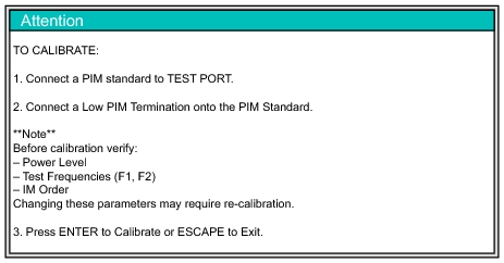
Attention, Calibration Message
3. Connect a PIM standard onto the test port of the PIM Master and connect a Low PIM Termination onto the PIM standard.
5. During the calibration, CALIBRATION IN PROCESS... is displayed on the measurement screen in red letters.
6. An attention message is displayed.
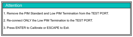
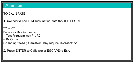
Attention, Calibration Message
7. Remove the PIM standard and the Low PIM Termination, and then connect only the Low PIM Termination onto the test port.
8. Press Enter to calibrate or Esc to exit.
9. During the calibration, CALIBRATION IN PROCESS... is displayed on the measurement screen in red letters.
10. When calibration is complete, Calibration On is displayed at the bottom of the Instrument Settings Summary.
Custom Calibration
A custom calibration is available to generate multiple PIM versus Time calibrations using the current frequency settings. Use this calibration when making PIM versus Time measurements at multiple power levels.
1. Press Shift then Cal (2).
2. In the Calibration menu, press the Custom Calibrations submenu key.
3. In the Custom Calibrations menu, press the Start Cal PIM vs. Time Only All Power Levels submenu key and follow the on-screen instructions (see Figure: Attention, Calibration Message).
Attention, Calibration Message
4. During calibration, an hourglass is displayed at the top of the measurement screen near the battery status icon.
5. When calibration is complete, Calibration On is displayed at the bottom of the Instrument Settings Summary (lower‑left corner of screen).
Verifying Residual PIM
Perform this test immediately following calibration while the Low PIM Termination is still connected to the Test Port.
1. From the Measurements menu, press the PIM vs. Time submenu key followed by the Test submenu key so that Measure is underlined.
2. Lightly tap on the Low PIM Termination during the PIM vs. Time test. The peak PIM value should be at least 10 dB below the pass/fail criteria for the DUT.
If the measured PIM is outside of the limit in Step 2, then you may have one of the following problems:
• Metal flakes inside one or more RF connectors
• Loose RF connector
• Faulty Low PIM Termination
• Worn connector saver
• Damaged Test Port connector
Investigate and repair the source of any problem, and then repeat the calibration process.
Verifying the PIM Standard
1. Connect a PIM Standard to the Test Port.
2. Connect a Low PIM Termination to the PIM Standard.
3. From the Measurements Menu, press the PIM vs. Time submenu key, followed by the Test submenu key so that Measure is underlined.
1 This value is N/A because at this measurement frequency, this PIM standard generates an IM3 level that is outside of the PIM Master measurement range.
Note
Typical values are shown. PIM Standards can vary ± 3 dB due to manufacturing variation. Record the starting value of your PIM Standard, and use that value for test equipment verification.
Verifying the Test Lead
Note
When testing, cables are connected and disconnected many times. In order to save wear on these test port cables, Anritsu recommends removing the o-rings. This allows getting a sufficiently tight connection without unnecessary stress on the connectors. In the field, o-rings are important to maintain connection integrity over long time periods. Connections must be torqued to specifications in order to ensure that they prevent water intrusion.
During your test, if the DUT connector has an o-ring, leave it in place and tighten to the correct torque.
Next, check the condition of the test lead. If you should accidently calibrate with an out‑of‑specification Low PIM termination, this verification will reveal the problem.
1. Connect a test port cable to the PIM Master and terminate the other end with a Low PIM Termination.
2. From the Measurements Menu, press the PIM vs. Time submenu key followed by the Test submenu key so that Measure is underlined.
3. During the test, flex the test lead and verify that the PIM level of the test lead and the Low PIM Termination are at least 10 dB below the pass / fail criteria for the DUT.
If the test cable fails, inspect the connections to ensure that they are clean and tight. If poor performance persists, then repeat the calibration process.
4. If the PIM level of the setup is within specification, then disconnect the Low PIM Termination and connect the test port to the DUT for a PIM measurement.
Checking for External Interference
Before performing a PIM test on an antenna system, verify that external interference is not present at the selected IM frequency.
1. Connect a test port cable from the PIM Master to the DUT.
2. Press the Measurements main menu key and then press Noise Floor to open the Noise Floor submenu.
3. From the Noise Floor submenu, press the Test submenu key so that Measure is underlined.
4. Verify that the external noise level at the selected IM frequency is below the required system pass / fail threshold for PIM.
Making PIM Measurements
1. Press the Measurements main menu key and then press one of the measurement submenu keys (PIM vs. Time, Distance‑to‑PIM, or Swept PIM).
2. From the Measurements menu, press the Test submenu key so that Measure is underlined.
3. During a PIM versus Time test, tap connectors and the antenna.
Note: Set the test duration time so that you can tap all desired areas.
4. After the measurement is complete, press the Save Measurement submenu key, provide an appropriate name, and save the measurement. (Refer to File Management.)
Note
The PIM Master continually monitors Return Loss at the two PIM test frequencies. If the Return Loss exceeds –6 dB, then the PIM test will be terminated, and a warning message will appear saying, “Warning! High Reflection from measurement path!”