Primary Cal Menu, Sub-Menus and Dialog Boxes – 4-Port VNAs
CALIBRATION [TR] Menu – 4-Port VNAs
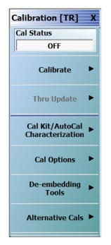
Use the CALIBRATION menu to setup calibration options, configure AutoCal and cal kit characterization files, and to configure and run calibration routines.
The CALIBRATION menu is not available when using the Spectrum Analysis application.
Full Name
Calibration [Transmission-Response]
The name of the Calibration menu is appended with [TR] for transmission/reflection operational mode. The instrument operation mode is set on the Application Menu. See Application Menus – Overview.
The Cal Status toggle button displays the calibration status based on the last calibration run.
If not calibrated, Cal Status cannot be changed from OFF and a calibration run must be successfully completed before the status can be changed.
If calibrated, Cal Status status can be toggled between OFF and ON. If ON, the Channel Status bar at the bottom of the display area shows a status of CORR in green.
Calibrate
Use the Calibrate button to start the AutoCal or manual calibration process. Options on sub-menus allow for selection of automatic or manual calibration, calibration type, calibration method, line type and other calibration parameters. Select displays the CALIBRATE menu.
Thru update is a calibration refreshing technique where the user connects a thru line and quickly refreshes the transmission tracking and load match terms without the time and complexity of a full calibration run. The thru update is essentially a one-step refresh calibration for Full 2 Port and 1 Path-2 Port calibrations.
Select displays the THRU UPDATE menu. If the Thru Update button is not available, a Full 4-Port, Full 3-Port, Full 2-Port, or 1 Path-2 Port calibration is not active. Complete one of the required calibrations to activate the Thru Update button.
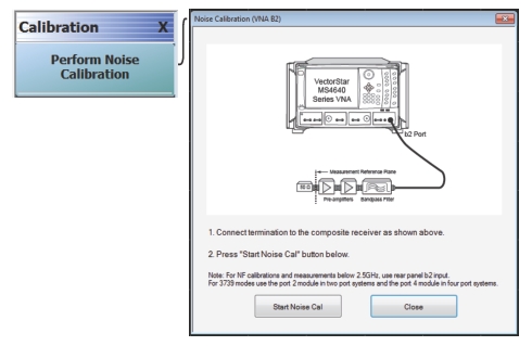
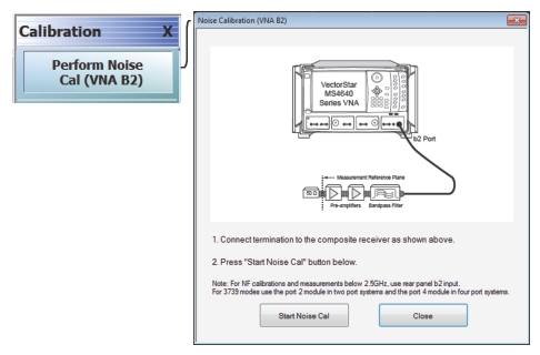
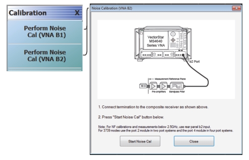
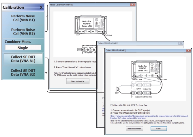
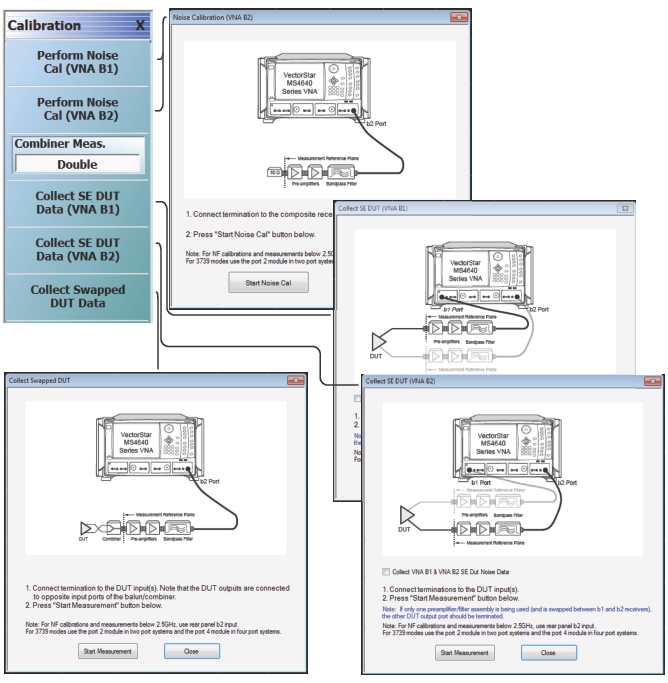
When Noise Figure (Option 41) or Differential Noise Figure (Option 48) is active (see Noise Figure (Option 41) or Differential Noise Figure (Option 48)), selecting Calibration from Main Menu opens a modified Calibration [Noise Figure] menu, which varies depending on DUT configuration and Noise Cal Method. Use the Calibration menu to perform noise calibrations, which remove the noise added by the composite receiver chain(s). .
CALIBRATION Menu – Noise Figure, Option 41
CALIBRATION Menu – Noise Figure, Option 48, 2-Port DUT
CALIBRATION Menu – Noise Figure, Option 48, 4-Port DUT
CALIBRATION Menu – Noise Figure – Option 48 with 4-Port DUT Configuration, Single Combiner Measurement
CALIBRATION Menu – Noise Figure – Option 48 with 4-Port DUT Configuration, Double Combiner Measurement
CALIBRATE Menu – 4-Port VNAs
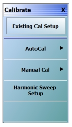
Use the CALIBRATE menu to start the AutoCal or manual calibration process. Sub-menus within each category allow selection of calibration parameters, calibration types, calibration methods, line types, and test port connectors.
• MAIN | Calibration | CALIBRATION | Calibrate | CALIBRATE
CALIBRATE Menu – 4-Port VNAs
Existing Cal Setup
Restores the setup parameters from the last successful calibration procedure, whether an AutoCal or manual calibration. All menu and dialog box settings are returned to their prior settings and the operator can proceed with the calibration procedure as soon as the necessary external device connections are complete.
Select displays the Harmonic Sweep dialog box. This selection is available only when Frequency Sweep (Linear) mode is selected from the SWEEP TYPES Menu.
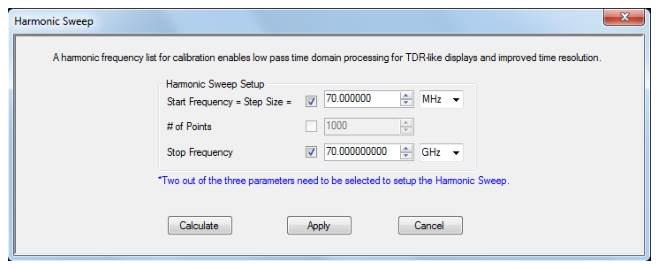
When in Frequency Sweep (Linear) mode, selecting Harmonic Sweep Setup from the Calibrate menu opens the dialog shown below. This is available only when the VNA is in Frequency Sweep (Linear) mode.
By using Harmonic Sweep, a harmonic frequency list for calibration enables low pass time domain processing for TDR (Time Domain Reflectometer)-like displays and improved time resolution.
Two of the three parameters (Start Frequency or Number of Points or Stop Frequency) must be selected in order to set the harmonic sweep. The value of the third parameter is adjusted according to the other two.
Even with one free parameter, the entered numbers may not be consistent with a harmonic sweep. Pressing the Calculate button will coerce values to make a valid harmonic sweep and allow the user to fine tune values before leaving the dialog.
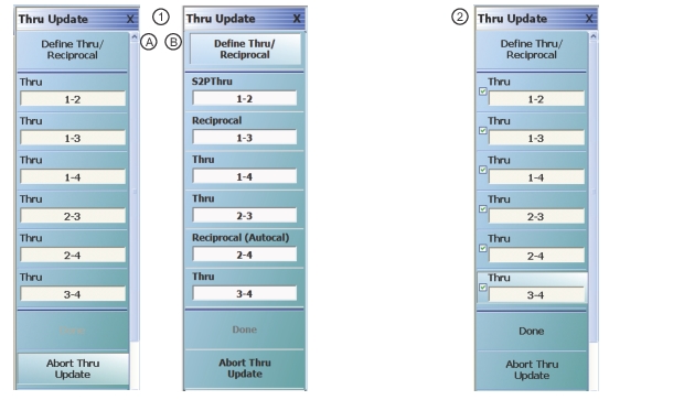
THRU UPDATE Menu – 4-Port VNAs
The THRU UPDATE menu is a completion button menu. When the through update calibration procedure is complete, the button is annotated with a completion checkmark as shown in the figure below
• The Thru Update button on the CALIBRATION menu is not available unless a Full 4-Port, Full 3-Port, Full 2-Port, or a 1 Path-2 Port calibration has been successfully completed.
• The number of Thrus and the Thru pairs presented depends on the user-defined calibration configuration.
1. Starting THRU UPDATE calibration menus for 4-Port VNA system. The Done button is unavailable. The number of thrus and the thru pairs presented depends on the user configuration before the calibration and thru update.
2. At right, the completed THRU UPDATE calibration menu for 4-port VNA system on right with completion check marks and Done button available.
Define Thru/Reciprocal
Displays the THRU INFO dialog box where the through parameters can be changed.
The number of Thru buttons to appear depend on which were selected during the setup. The possible thru selections in a 4-Port system are 1-2, 1-3, 1-4, 2-3, 2-4, and 3-4. In the example menu above (Callout #1B), all available 4-Port Thru measurements are required.
Reciprocal
Reciprocal is not valid with 1-2 and 3-4 paths.
Reciprocal (Autocal)
Reciprocal (AutoCal) is not valid with 1-2 and 3-4 paths.
Done
When all calibrations are successfully completed, the Done button is available. Select returns to the CALIBRATION menu and the Cal Status button is set to ON.
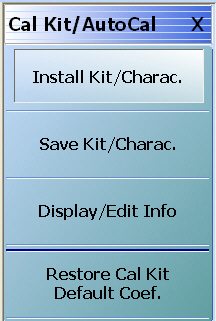
Use the CAL KIT/AUTOCAL menu to install, save, and restore calibration kit characterization files between an external memory device, the instrument firmware, and a hard drive on the instrument or on a network.
Full Name
Full Manual Calibration Kit / Automatic Calibrator (AutoCal)
• MAIN | Calibration | CALIBRATION | Cal Kit/AutoCal Characterization | CAL KIT/AUTOCAL
CAL KIT/AUTOCAL Menu – 4-Port VNAs
Install Kit/Charac.
Select loads the Calibration Kit file or AutoCal Characterization file from the hard drive or external memory device into the VNA firmware through the INSTALL (AutoCal Characterization/Cal Kit File) dialog box.
Select saves the Cal Kit or AutoCal Characterization file from the firmware to the location of choice (typically the instrument hard drive) for later use through the SAVE (AutoCal Characterization/Cal Kit) File dialog box.
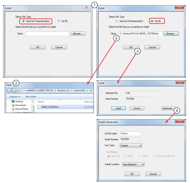
Use the INSTALL (AUTOCAL CHARACTERIZATION/CAL KIT) dialog box to install the Cal Kit Coefficients file or AutoCal Characterization files in the instrument firmware for subsequent use. A recommended best practice is to keep the cal kit serial number as part of the file name.
1. In the Select File Type area, select either the AutoCal Characterization or the Cal Kit radio button.
2. In the Open field, either enter the file name or click Browse to navigate manually.
• If AutoCal Characterization was selected, the file type will be an AutoCal Characterization ACD file.
• If Cal Kit was selected, the file type choices will be:
• Cal Kit Coefficient (CCF file)
• S1P/S2P Files (LST file)
• LRL/LRM-TRL/TRM Cal Kit Files (LCF file)
• MTRL Cal Kit Files (MLCF file)
• Lightning Files
• Click Open to load the file or Cancel to return to the menu.
3. Clicking OK to accept opens the Install window. Click the Install button to load the file.
4. Clicking the Advanced button opens the Install (Advanced) dialog where the user can change the Cal Kit Label,Line Type, or the Install Locationto install the LST CalKit to a User Defined install location.
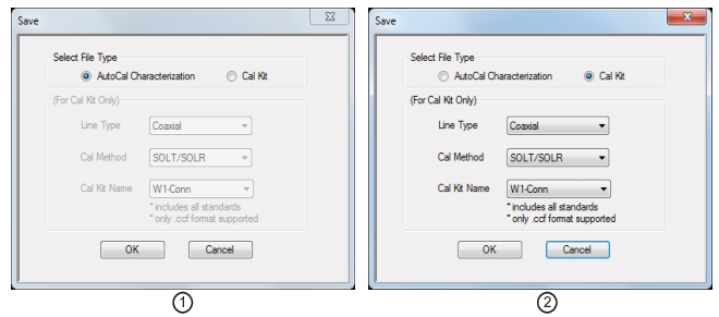
SAVE (AUTOCAL CHARAC./CAL KIT) Dialog Box – 4-Port VNAs
Use the SAVE (AUTOCAL CHARACTERIZATION/CAL KIT) dialog to save a Calibration Kit Coefficients file or an AutoCal Characterization file from the VNA firmware to external location such as the instrument hard drive, a network drive, or an external memory device. This is useful for storing in the instrument hard drive multiple files from available cal kits or AutoCal modules.
An alternate method is to a Windows program such as File Manager to copy the file from the supplied USB memory device onto the hard drive. In that case, we recommend using the default locations mentioned later in this paragraph.
• MAIN | Calibration | CALIBRATION | Cal Kit/AutoCal Characterization | CAL KIT/AUTOCAL | Save Kit/Charac | SAVE (AUTOCAL CHARACTERIZATION/CAL KIT) Dialog Box
SAVE (AUTOCAL CHARACTERIZATION/CAL KIT FILE Dialog Box
1. AutoCal Characterization radio button selected. 2. Cal Kit radio buttons selected.
Save Dialog Button and Field Availability
The available buttons and fields on the dialog depend on the radio button selection in the Select File Type area.
• If AutoCal Characterization is selected, no other buttons/fields are available and instructions are immediately below.
• If Cal Kit is selected, the For Cal Kit Only area becomes available with fields for Line Type, Cal Method, and Cal Kit Name. Instructions are in the next sub-section following.
Instructions for AutoCal Characterization File Type
1. Click OK to save the AutoCal Characterization file.
• Click Cancel to stop the save.
2. The SAVE AS (AUTOCAL CHARACTERIZATION ACD FILE) dialog box appears.
3. Navigate to the required storage location:
• C:\AnritsuVNA\AutoCal is recommended.
4. Click Save. The system auto-returns to the Cal Kit/AutoCal menu.
• MAIN | Calibration | CALIBRATION | Cal Kit/AutoCal Characterization | CAL KIT/AUTOCAL | Display/Edit Info | CAL KIT INFO Dialog Box
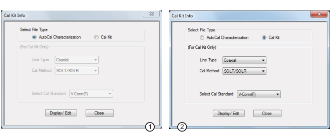
CAL KIT INFO Dialog Box
1. At left, controls for AutoCal Characterization files. 2. At right, controls for Cal Kit files.
Button and Field Availability
The available buttons and fields on the dialog depend on the radio button selection in the Select File Type area.
• If AutoCal Characterization is selected, no other buttons/fields are available.
• If Cal Kit is selected, the For Cal Kit Only area becomes available with fields for Line Type, Cal Method, and Select Cal Standard.
Instructions
1. Select AutoCal Characterization or Cal Kit as required.
2. If Cal Kit was selected above, in the For Cal Kit Only area, select a Line Type value:
• Coaxial
• Non-Dispersive
• Microstrip
• Waveguide
3. Select a Cal Method value:
• SOLT/SOLR
• SSLT
• SSST
• SOLT/R-SSST/R (for Broadband)
4. Select a Cal Standard value:
• 0.8 mm-Conn (M)
• 0.8 mm-Conn (F)
• W1-Conn (M)
• W1-Conn (F)
• V-Conn (M)
• V-Conn (F)
• K-Conn (M)
• K-Conn (F)
• 2.4 mm (M)
• 2.4 mm (F)
• GPC-3.5 (M)
• GPC-3.5 (F)
• SMA (M)
• SMA (F)
• N-Conn (M)
• N-Conn (F)
• N-Conn (75) (M)
• N-Conn (75) (F)
• GPC-7
• 7/16 (M)
• 7/16 (F)
• TNC (M) (Kit from Maury Microwave)
• TNC (F) (Kit from Maury Microwave)
• User-Defined1(M) through User-Defined32 (M)
• User-Defined1(F) through User-Defined32 (F)
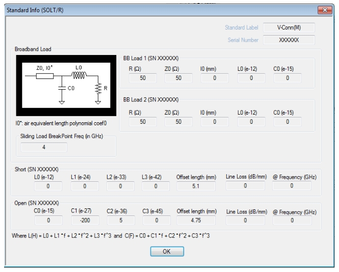
5. Click Display/Edit.
• The STANDARD INFO read-only dialog box appears.
• Note that the dialog box title and content fields are dependent on the selections made in the steps above for Cal Method, Line Type, and Connector Type.
• For example, if:
• Calibration type is set to Full 2 Port (12 Term Cal)
STANDARD INFO (SOLT/R) Standard Label (V-Conn (M)) Dialog Box
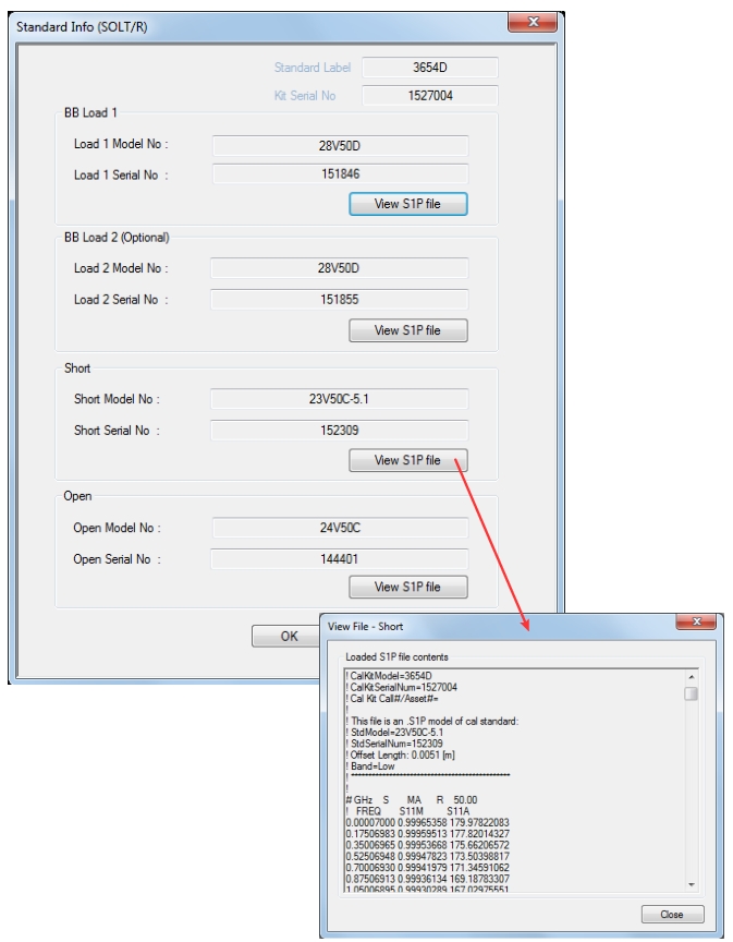
STANDARD INFO (SOLT/R) Standard Label (V-Conn (M)) Dialog Box – Loaded from LST file.
RESTORE DEFAULT COEF. Dialog Box – 4-Port VNAs
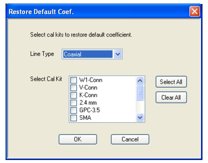
Use the RESTORE DEFAULT COEF. dialog box to restore firmware-stored Cal Kit Coefficients fields back to their default coefficients. For best performance, either install the cal kit coefficients file supplied with your cal kit, or enter your user-defined coefficients before starting this procedure. The restore function is not available to AutoCal kits as they do not have restorable characterization data.
Use this dialog to restore factory coefficients to available calibration kits.
1. Select the Line Type as required.
2. Select the Calibration Kits as required to be restored.
3. Click OK.
Available Selections
The table below shows the available calibration kits in the Select Cal Kit field of the RESTORE DEFAULT COEFFICIENTS dialog box. The available kits depend on the input combination selected for Line Type Media and Cal Method
Calibration Kit Availability in the RESTORE DEFAULT COEF. Dialog Box
LINE TYPE Media Setting
CAL METHOD Setting
Available Calibration Kits
Coaxial
SOLT/SOLR
0.8 mm-Conn, W1-Conn, V-Conn, K-Conn, 2.4 mm, 2.4 mm V, GPC-3.5, SMA, N-Conn, N-Conn (75), GPC-7, 7/16, TNC
The CAL OPTIONS menu and related sub-menus provide access to advanced calibration options either before or after a calibration procedure has been completed.
• MAIN | Calibration | CALIBRATION | Cal Options | CAL OPTIONS
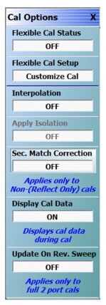
CAL OPTIONS (CALIBRATION OPTIONS) Menu
Flexible Cal Status (Off/On)
Read only display button. Flexible calibration is the ability to select a sub-set of a currently active calibration status. For example, if a Full 2 Port calibration has been completed, flexible calibration allows the calibration to be reduced to a Transmission Frequency Response calibration. Select toggles flexible calibration off and on.
Flexible Cal Setup
Use Flexible Cal Setup to change the parameters above. Select displays the FLEXIBLE CAL SETUP dialog box.
Interpolation allows additional interpolated measurement points between calibrated measurement points. This is useful if the user wants to zoom into a specific area without having to recalibrate the instrument. The interpolated points must lie within the calibration frequency points. Select toggles interpolation OFF and ON with a default state of OFF.
Apply Isolation (Off/On)
If this button is unavailable, isolation calibration was not performed. The isolation calibration procedure is started by a button on the calibration type menu.
If this button is available, isolation calibration was performed, and select toggles isolation calibration OFF and ON.
Sec. Match Correction (Off/On)
Secondary Match Correction provides a calibration enhancement that reduces high-spatial‑frequency ripple by removing the effects of the multiple reflection paths within a DUT. Default value is OFF. This feature only applies for full-term calibrations, 1p2p and TFR. This function has no effect when an appropriate calibration is not applied, when the frequency range is too small (~<2GHz), the step size is too large (~>1 GHz) or for certain very irregular segmented sweep setups. See the Measurement Guide for more details.
Display Cal Data (On/Off)
When turned on, the Display Cal Data function enables the use of a previous calibration to provide a real-time quasi-corrected view of the current standard being measured. Select toggles Display Cal Data OFF and ON. The default state is ON.
Update On Rev. Sweep (On/Off)
When turned on, updates display data only on the reverse sweep. When turned off, updates display data on every sweep. This feature is only available on 2 port systems and is only used when a full 2-port RF cal is applied. Select toggles Update On Rev. Sweep ON and OFF. The default state is OFF.
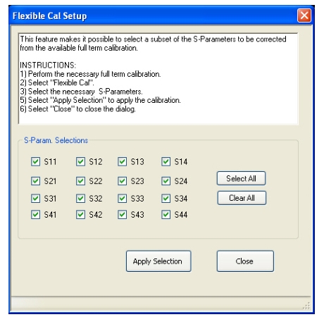
FLEXIBLE CAL SETUP Dialog Box – 4-Port VNAs
Use the Flexible Cal Setup dialog box to define a calibration sub-set of the currently active calibration.
The flexible calibration setup feature makes it possible to select a subset of the S-Parameters to be corrected from the available full-term calibration.
Procedure
1. Perform the necessary full-term calibration.
2. Navigate to the FLEXIBLE CAL SETUP dialog box appears:
• MAIN | Calibration | CALIBRATION | Cal Options | CAL OPTIONS | Flexible Cal Setup | FLEXIBLE CAL SETUP
3. Select the input method (full term, reflection only, or customize). The default selection is full term calibration with all the ports turned on for the available calibration type. The following radio button options are available in the Input Method area:
• Full Term Cal (By Port)
• Reflection Only (By Port)
• Customize Cal (By S-Param)
4. If Full Term Cal (By Port) is selected above, the area label is Port Selections (Full Term) with available options of:
• Port 1 and/or
• Port 2
5. If Reflection Only (By Port) is selected above, the area label is Port Selections (Reflection Only) with the available options of:
• Port 1 and/or
• Port 2
6. If Customize Cal (By S-Param) is selected, the S-Param Selections area appears with S-Parameter selection check boxes. Select any combination of:
• S11
• S21
• S12
• S22
7. Select Apply Selection to apply the selections.
8. Select Close to close the dialog without saving the selections.
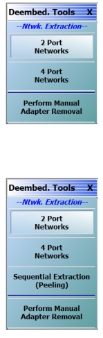
DEEMBED. TOOLS Menu – 4-port VNAS
Use the DEEMBED. TOOLS menu to for network extraction and adapter removal.
Use network extraction to generate an S-Parameter (.s2p) file for a set of networks. The file can be embedded or de-embedded as required. Select displays the 2-Port NETWORK EXTRACTION dialog box.
Use network extraction to generate an S-Parameter (.s2p or .s4p) file for a set of networks. The file can be embedded or de-embedded as required. Select displays the 4-Port NETWORK EXTRACTION dialog box.
Sequential Extraction will construct a .s2p or .s4p file based on a localization of the selected parameter to isolate a given defect. This process can be used to sequentially de-embed and identify additional defects.
Adapter removal permits accurate measurement of non-insertable devices using an adapter of known electrical length and two full 12-term calibrations. Manual adapter removal extracts the behavior of the adapter from the setup after a successful calibration. Select displays the MANUAL ADAPTER REMOVAL dialog box.
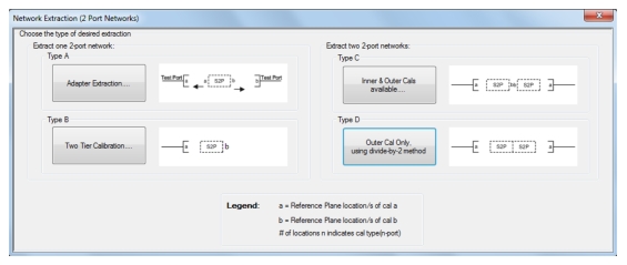
NETWORK EXTRACTION Main Dialog – 4-Port VNAs (without Option 21)
Network extraction provides a method of generating an S-Parameter (S2P or S4P) file for a set of networks. The S2P or S4P file can then be embedded or de-embedded into the VNA’s error coefficient as required.
• MAIN | Calibration | CALIBRATION | De-embedding Tools | DEEMBED. TOOLS | 2 Port Networks| NETWORK EXTRACTION (2 Port Networks) Dialog Box
NETWORK EXTRACTION (2 Port Networks) Dialog Box – 4-Port VNAs
Navigation: Network Extraction (4-Port Networks)
• MAIN | Calibration | CALIBRATION | De-embedding Tools | DEEMBED. TOOLS | 4 Port Networks| NETWORK EXTRACTION (4 Port Networks) Dialog Box
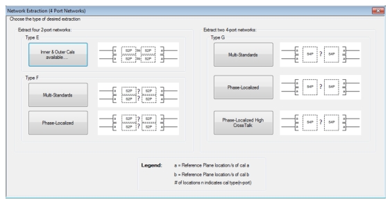
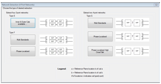
NETWORK EXTRACTION (4 Port Networks) Dialog Box – 4-Port VNAs
NETWORK EXTRACTION Main Dialog – 4-Port VNAs (with Option 21)
Network extraction provides a method of generating an S-Parameter (S2P or S4P) file for a set of networks. The S2P or S4P file can then be embedded or de-embedded into the VNA’s error coefficient as required.
1 For more information on Type B, Type D, Type F, Type G, and Sequential Extraction with Option 21 installed, refer to the Measurement Guide (10410-00218).
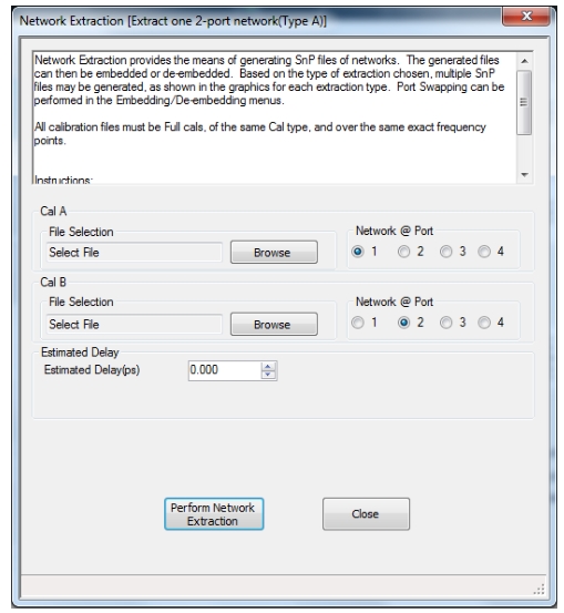
NETWORK EXTRACTION Dialog Box – Type A
Full Name
Network Extraction [Extract One 2-Port Network (Type A)]
6. After the .SnP files have been saved, go to Measurement | Edit Embed/De-embed | Edit Network Configuration panel to recall the .SnP files and configure the network.
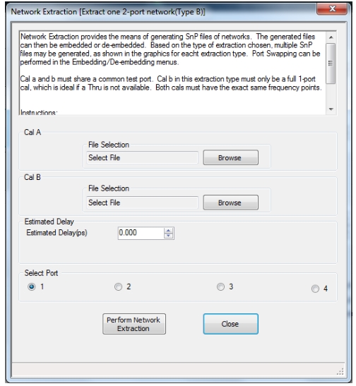
NETWORK EXTRACTION Dialog Box – Type B
Full Name
Network Extraction [Extract One 2-Port Network (Type B)]
• MAIN | Calibration | CALIBRATION | De-embedding Tools | DEEMBED. TOOLS | Ntwk. Extraction | 2 Port Networks | NETWORK EXTRACTION (2 Port Networks) Dialog Box | Extract One 2-Port Network | Type B – Two Tier Calibration – With Full Standards | NETWORK EXTRACTION [EXTRACT ONE 2-PORT NETWORK (TYPE B)] Dialog Box
NETWORK EXTRACTION – EXTRACT ONE 2-PORT NETWORK – TYPE B
Instructions
Network Extraction provides the means of generating SnP files of networks. Port Swapping can be performed in the Embedding/De-embedding menus.
Cal A and Cal B must share a common test port. Cal A in this extraction type must only be a full 1-port cal, which is ideal if a Thru is not available. Both cals must have the exact same frequency points.
Procedure
1. Use the Browse button to select the appropriate cal file(s).
2. If necessary, enter Estimated Delay in ps.
3. Select Perform Network Extraction to perform the extraction.
4. If the extraction is successful, follow the prompt to save the generated SnP file(s).
6. After the .s2p files have been saved, go to Measurement | Edit Embed/De-embed | Edit Network configuration panel to recall the .s2p files and configure the network.
NETWORK EXTRACTION Dialog Box – Type B – With Flex Standards (Option 21)
Full Name
Network Extraction [Extract One 2-Port Network (Type B – Flex Standards)]
Note that Type B with Flex Standards (Generalized B) is available only with Option 21.
• A full term calibration needs to exist and be active.
Navigation
• MAIN | Calibration | CALIBRATION | De-embedding Tools | DEEMBED. TOOLS | Ntwk. Extraction | 2 Port Networks | NETWORK EXTRACTION (2 Port Networks) Dialog Box | Extract One 2-Port Network | Type B | Two Tier Calibration With Flex Standards | NETWORK EXTRACTION [EXTRACT ONE 2-PORT NETWORK (TYPE B- FLEX STANDARDS)] Dialog Box
NETWORK EXTRACTION – EXTRACT ONE 2-PORT NETWORK – TYPE B – FLEX STANDARDS
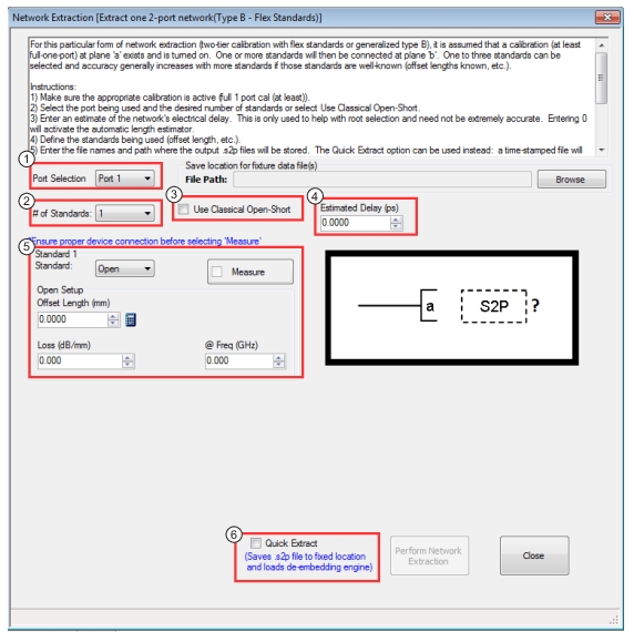
1. Port Selection: Ports 1-4 available (with 4-Port VectorStar)
2. # of Standards: Three standards available; corresponding setup fields appear for up to four standards.
3. Use Classical Open-Short: Checking box sets up a special case of the 2-standards scenario where a zero offset open and short are used and the fixture arm is assumed to be electrically short. When selected, dialog options adjust as shown in Figure: Type B – With Flex Standards Extraction Setup Fields (1 of 2).
4. Estimated Delay (ps): Here an estimate of the network's electrical delay is entered. This is only used to help with root selection and need not be extremely accurate. Entering 0 will activate the automatic length estimator.
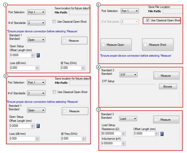
Type B – With Flex Standards Extraction Setup Fields (1 of 2)
1. Selecting Short from the dropdown opens the setup options as shown.
2. Selecting Open from the dropdown opens the setup options as shown.
3. Selecting Load from the dropdown opens the setup options as shown.
4. Selecting S1P from the dropdown opens the setup options as shown.
5. Checking the Use Classical Open-Short box opens the setup options as shown. This selection sets up a special case of the 2-standards scenario where a zero offset open and short are used and the fixture arm is assumed to be electrically short. When selected, dialog options adjust as shown.
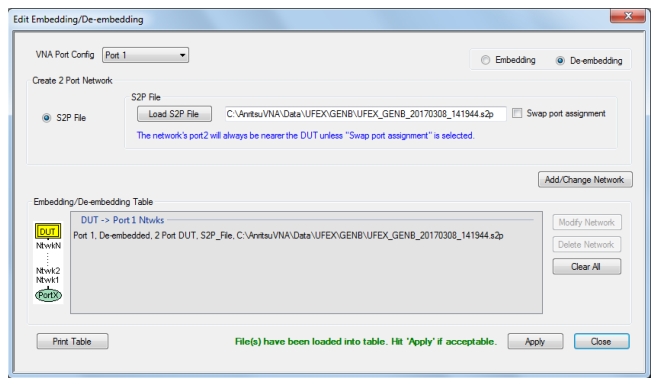
If the option Quick Extract is selected, and after Perform Network Extraction is executed, the above dialog appears with a pre-loaded Networks table using newly created .SnP files.
Instructions
Network Extraction provides the means of generating SnP files of networks. The generated files can then be embedded or de-embedded. Port Swapping can be performed in the Embedding/De-embedding menus.
For this particular form of network extraction (two-tier calibration with flex standards or generalized type B), it is assumed that a calibration (at least full-one-port) at plane 'a' exists and is turned on. One or more standards will then be connected at plane 'b'. One to three standards can be selected and accuracy generally increases with more standards if those standards are well-known (offset lengths known, etc.).
Procedure (Use Classical Open-Short Is Not Selected)
1. Make sure the appropriate calibration is active (full 1 port cal (at least)).
2. Select the port being used and the desired number of standards.
3. Enter an estimate of the network's electrical delay. This is only used to help with root selection and need not be extremely accurate. Entering 0 will activate the automatic length estimator.
4. Define the standards being used (offset length, etc.). Note if two standards are of the same type, they should have different parameters.
5. Enter the file names and path where the output .s2p files will be stored. The Quick Extract option can be used instead: a time-stamped file will be saved to a predetermined hard disk location and the de-embedding engine will automatically load those files. Remember to keep track of available disk space.
6. Connect each standard sequentially and click the appropriate Measure button when ready. When the sweep is complete, a check will appear in the box and the button will turn green.
7. When all desired standards have been measured, click on Perform Network Extraction. If successful, a confirmation dialog will appear.
9. If Quick Extract was not selected, after the .s2p files have been saved, go to Measurement | Edit Embed/De-embed | Edit Network configuration panel to recall the .s2p files and configure the network.
Procedure (Use Classical Open-Short Is Selected)
1. Select the port being used.
2. Enter an estimate of the network's electrical delay. This is only used to help with root selection and need not be extremely accurate. Entering 0 will activate the automatic delay estimator.
3. Enter the file names where the output .s2p files will be stored. The Quick Extract option can be used instead: the file will be saved to a predetermined hard disk location and the de-embedding engine will automatically load those files.
4. Connect each standard sequentially and click the appropriate Measure button when ready. When the sweep is complete, a check will appear in the box and the button will turn green.
5. When all desired standards have been measured, click on Perform Network Extraction.
7. If Quick Extract was not selected, after the .s2p files have been saved, go to Measurement | Edit Embed/De-embed | Edit Network configuration panel to recall the .s2p files and configure the network.
NETWORK EXTRACTION Dialog Box – Type C
Full Name
Network Extraction – Type C – Extract Two 2-Port Networks – Inner and Outer Cals Available – 4-Port VNAs
• MAIN | Calibration | CALIBRATION | De-embedding Tools | DEEMBED. TOOLS | Ntwk. Extraction | 2 Port Networks | NETWORK EXTRACTION (2 Port Networks) Dialog Box | Extract Two 2-Port Networks | Type C – Inner and Outer Cals Available | NETWORK EXTRACTION [EXTRACT TWO 2-PORT NETWORKS (TYPE C)] Dialog Box
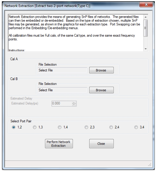
NETWORK EXTRACTION – EXTRACT TWO 2-PORT NETWORKS – TYPE C – 4-Port
Description
Network Extraction provides the means of generating SnP files of networks. The generated files can then be embedded or de-embedded. Port Swapping can be performed in the Embedding/De-embedding menus.
All calibration files must be Full cals, of the same Cal type, and over the same exact frequency points.
Instructions:
1. Use the Browse button to define the appropriate cal file(s) path. Note that CalB is the inner file and CalA is the outer file.
2. Select Perform Network Extraction to perform the extraction.
3. If the extraction is successful, follow the prompt to save the generated SnP files(s).
5. After the .SnP files have been saved, go to Measurement | Edit Embed/De-embed | Edit Network configuration panel to recall the .SnP files and configure the network.
NETWORK EXTRACTION Dialog Box – Type D (No Option 21)
Full Name
Network Extraction [Extract two 2-port networks (Type D)]
• MAIN | Calibration | CALIBRATION | De-embedding Tools | DEEMBED. TOOLS | Ntwk. Extraction | 2 Port Networks | NETWORK EXTRACTION (2 Port Networks) Dialog Box | Type D – Outer Cal Only Using Divide-By-Two Method | NETWORK EXTRACTION [EXTRACT TWO 2-PORT NETWORKS (TYPE D)] Dialog Box
NETWORK EXTRACTION – EXTRACT TWO 2-PORT NETWORKS – TYPE D – 4-Port (No Option 21)
Description
Network Extraction provides the means of generating SnP files of networks. The generated files can then be embedded or de-embedded. Port Swapping can be performed in the Embedding/De-embedding menus.
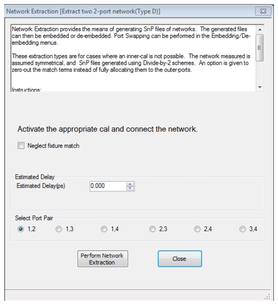
These extraction types are for cases where an inner-cal is not possible. The network measured is assumed symmetrical, and SnP files generated using Divide-by-2 schemes. An option is given to neglect fixture match terms instead of fully allocating them to the outer-ports.
Procedure
1. Make sure the appropriate calibration is active.
2. Select Neglect fixture match terms if needed (this sets all reflection terms to 0 and may be helpful if the fixture is extremely unrepeatable).
3. Connect the network and select Perform Network Extraction.
4. If the extraction is successful, follow the prompt to save the generated SnP files/s.
5. After the .SnP files have been saved, go to Measurement | Edit Embed/De-embed | Edit Network configuration panel to recall the .SnP files and configure the network.
NETWORK EXTRACTION Dialog Box – Type D – Multi-Standards (Option 21)
Full Name
Network Extraction [Extract two 2-port networks (Type D – Multi-Standards)]
• A full term calibration needs to exist and be active.
Navigation
• MAIN | Calibration | CALIBRATION | De-embedding Tools | DEEMBED. TOOLS | Ntwk. Extraction | 2 Port Networks | NETWORK EXTRACTION (2 Port Networks) Dialog Box | Type D – Outer Cal Only Using Divide-By-Two Method | NETWORK EXTRACTION [EXTRACT TWO 2-PORT NETWORKS (TYPE D – MULTI-STANDARDS)] Dialog Box
NETWORK EXTRACTION – EXTRACT TWO 2-PORT NETWORKS – TYPE D – Multi Standard – 4-Port
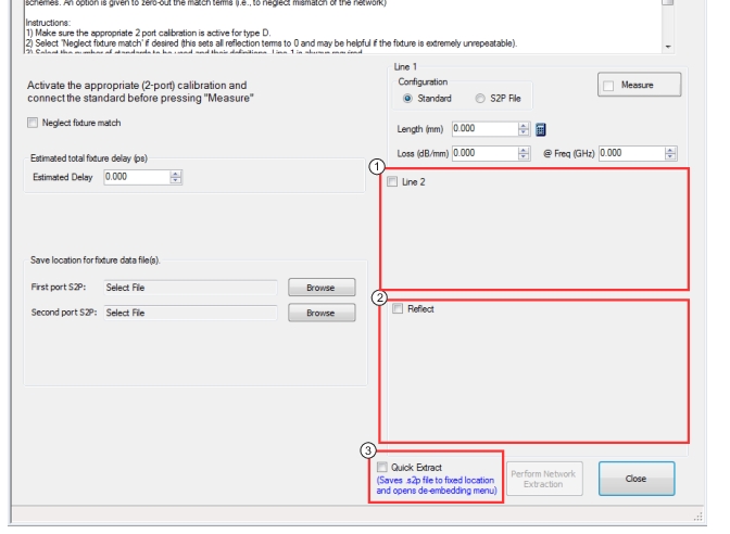
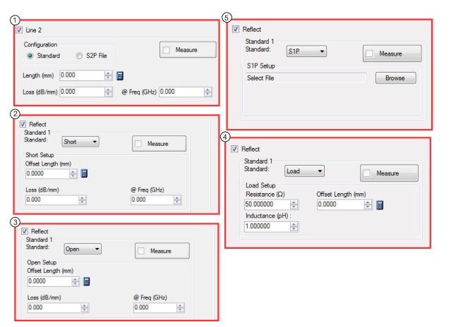
TYPE D – Multi Standard Dialog – Extraction Setup Fields
1. Checking Line 2 Length opens a dialog to adjust length.
2. Checking Reflect and selecting Short from the dropdown provides the dialog shown.
3. Checking Reflect and selecting Open from the dropdown provides the dialog shown.
4. Checking Reflect and selecting Load from the dropdown provides the dialog shown.
5. Checking Reflect and selecting S1P from the dropdown provides the dialog shown.
Instructions
Network Extraction provides the means of generating SnP files of networks. The generated files can then be embedded or de-embedded. Port Swapping can be performed in the Embedding/De-embedding menus.
These extraction types are for cases where an inner-cal is not possible. The network measured is assumed symmetrical, and SnP files generated using Divide-by-2 schemes. An option is given to neglect fixture match terms (i.e., to neglect mismatch of the network)
Procedure
1. Make sure the appropriate calibration is active (2 port cal (at least)) for Type D.
2. Select Neglect fixture match if needed (this sets all reflection terms to 0 and may be helpful if the fixture is extremely unrepeatable).
3. Select the path of interest or indicate how the dominant transmission paths are aligned (e.g., if the network is a differential pair with port 1 connected to port 2 with high transmission and port 3 is connected to port 4 with high transmission, and the other paths like 1-3 and 2-3 are high loss, then select 1-2 (and 3-4).
4. Select the number of standards to be used and their definitions. Line 1 is always required.
5. Connect each standard (or standards in the case of Reflect; all ports must have the Reflect connected simultaneously) before pressing Measure.
6. Enter the file names where the output .s2p files will be stored. The Quick Extract option can be used instead: files will be saved to a predetermined hard disk location and the de-embedding engine will automatically load those files. Remember to keep track of available disk space.
7. When all fields have been entered and all standards measurements have been completed (all of the check boxes marked and the buttons turn green), press Perform Network Extraction. If successful, a confirmation dialog will appear.
9. If Quick Extract was not selected, after the .s2p files have been saved, go to Measurement / Edit Embed/De-embed / Edit Network configuration panel to recall the .s2p files and configure the network.
NETWORK EXTRACTION Dialog Box – Type D – Phase Localized (Option 21)
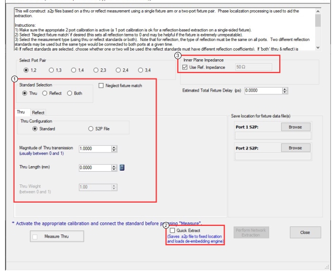
3. Note that for Inner Plane Impedance, the New Impedance entry is only shown if Use Ref. Impedance is not checked. The Text box next to the “Use Ref. Impedance” is read-only and displays the ref. impedance of the channel.
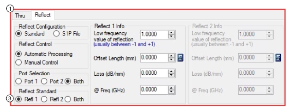
TYPE D – Phase Localized Dialog – Reflect Extraction Setup Variations
1. Checking Reflectand selecting Automatic Processing opens the dialog shown.
2. Checking Reflectand selecting Manual Control opens the dialog shown.
3. Note that the port selection labels under Reflect Setup are updated based on the Select Port Pair selection.
4. Note that when Manual Control is selected, the Delay to Central Fixture Interface Location is enabled.
Instructions
This will construct .s2p files based on a thru or reflect measurement using a single fixture arm or a two-port fixture pair. Phase localization processing is used to aid the extraction.
To do this phase localization, the frequency list must be relatively uniform (no CW or log sweep and segmented sweep step sizes should not deviate more than 3% from the mean) and the range should be large enough that the total fixture length (ns)>5/(frequency range (GHz)). The frequency step should be small enough that the total fixture length (ns) < 0.3/(Frequency step (GHz)).
1. Make sure the appropriate calibration is active for Type D.
2. Select Neglect fixture match terms if needed (this sets all reflection terms to 0 and may be helpful if the fixture is extremely unrepeatable).
3. Select the measurement type (using thru or reflect standards). Note that for Reflection, the type of reflection must be the same on all ports.
4. Define the standards being used (offset length, transmission or reflection magnitude, include the sign of reflection).
5. Enter an estimate of the network's electrical delay (both sides of the fixture pair). Entering 0 will activate the automatic length estimator. If using a reflect measurement, this can be further refined by selecting Manual Control where the fixture halves can be treated as asymmetric and only one side can be done if desired.
6. Enter the file names where the output .s2p files will be stored. The Quick Extract option can be used instead: time stamped files will be saved to a predetermined hard disk location and the de-embedding engine will automatically load those files. Remember to keep track of available disk space.
7. When all fields have been entered and proper connection has been made, click on Perform Network Extraction. If successful, files will automatically be saved and a confirmation dialog will appear.
9. If Quick Extract was not selected, after the .s2p files have been saved, go to Measurement / Edit Embed/De-embed / Edit Network configuration panel to recall the .s2p files and configure the network.
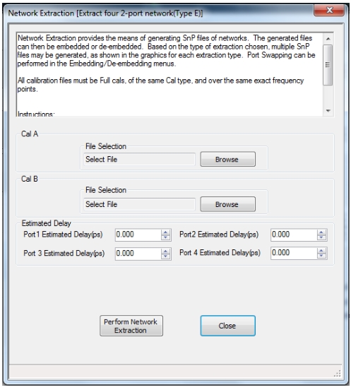
NETWORK EXTRACTION Dialog Box – Type E
Full Name
Network Extraction – Type E – Extract Four 2-Port Networks – Inner and Outer Cals Available – 4-Port VNAs
• MAIN | Calibration | CALIBRATION | De-embedding Tools | DEEMBED. TOOLS | Ntwk. Extraction | 4 Port Networks | NETWORK EXTRACTION (4-PORT NETWORKS) Dialog Box | Extract Four 2-Port Networks | Type E – Inner and Outer Cals Available | NETWORK EXTRACTION [EXTRACT FOUR 2-PORT NETWORKS (TYPE E)] Dialog Box
NETWORK EXTRACTION – EXTRACT FOUR 2-PORT NETWORKS – TYPE E – 4-Port
Instructions
Network Extraction provides the means of generating SnP files of networks. The generated files can then be embedded or de-embedded. Port Swapping can be performed in the Embedding/De-embedding menus.
All calibration files must be Full cals, of the same Cal type, and over the same exact frequency points.
Procedure
1. Select Browse to select the appropriate cal file(s).
2. Select Perform Network Extraction.
3. If the extraction is successful, follow the prompt to save the generated SnP file(s).
5. After the .SnP files have been saved, go to Measurement | Edit Embed/De-embed | Edit Network configuration panel to recall the .SnP files and configure the network.
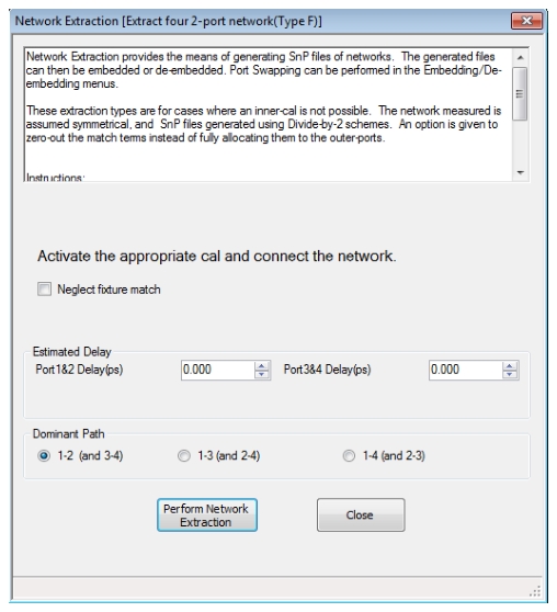
NETWORK EXTRACTION Dialog Box – Type F (No Option 21)
Full Name
Network Extraction – Type F – Extract Four 2-Port Networks – Inner and Outer Cals Available – 4-Port VNAs
• MAIN | Calibration | CALIBRATION | De-embedding Tools | DEEMBED. TOOLS | Ntwk. Extraction | 4 Port Networks | NETWORK EXTRACTION (4-PORT NETWORKS) Dialog Box | Extract Four 2-Port Networks | Type F – Outer Cal Only Using Divide-By-Two Method | NETWORK EXTRACTION [EXTRACT FOUR 2-PORT NETWORKS (TYPE F)] Dialog Box
NETWORK EXTRACTION – EXTRACT FOUR 2-PORT NETWORKS – TYPE F – 4-Port
Instructions
Network Extraction provides the means of generating SnP files of networks. The generated files can then be embedded or de-embedded. Port Swapping can be performed in the Embedding/De-embedding menus.
These extraction types are for cases where an inner-cal is not possible. The network measured is assumed symmetrical, and SnP files generated using Divide-by-2 schemes. An option is given to neglect fixture match terms instead of fully allocating them to the outer-ports.
Procedure:
1. Make sure the appropriate calibration is active.
2. Select Neglect fixture match terms if needed (this sets all reflection terms to 0 and may be helpful if the fixture is extremely unrepeatable).
3. Select the dominant paths of the network (i.e., the ports between which thrus are connected within the network assembly for the extraction).
4. Connect the network and select Perform Network Extraction.
5. If the extraction is successful, follow the prompt to save the generated SnP file(s).
6. After the .SnP files have been saved, go to Measurement | Edit Embed/De-embed | Edit Network configuration panel to recall the .SnP files and configure the network.
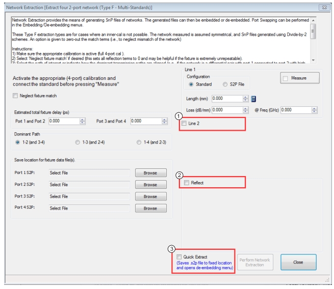
NETWORK EXTRACTION Dialog Box – Type F – Multi-Standards (Option 21)
Full Name
Network Extraction [Extract Four 2-port Networks (Type F-Multi-Standards)]
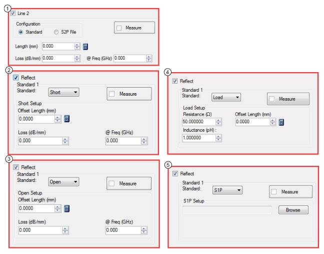
TYPE F – Multi-Standards – Extraction Setup Variations
1. Checking Line 2 Length box opens a dialog to adjust length.
2. Checking Reflect box and selecting Short from the dropdown opens the dialog as shown.
3. Checking Reflect box and selecting Open from the dropdown opens the dialog as shown.
4. Checking Reflect box and selecting Load from the dropdown opens the dialog as shown.
5. Checking Reflect box and selecting S1P from the dropdown opens the dialog as shown.
Instructions
Network Extraction provides the means of generating SnP files of networks. The generated files can than be embedded or de-embedded. Port Swapping can be performed in the Embedding/De-embedding menus.
These Type F extraction types are for cases where an inner-cal is not possible. The network measured is assumed symmetrical, and SnP files generated using Divide-By-2 schemes. An option is given to neglect fixture match terms (i.e., to neglect mismatch of the network).
Procedure
1. Make sure the appropriate calibration is active (a full 4-port cal for Type F).
2. Select Neglect fixture match if needed (this sets all reflection terms to 0 and may be helpful if the fixture is extremely unrepeatable).
3. Select the path of interest or indicate how the dominant transmission paths are aligned (e.g., if the network is a differential pair with port 1 connected to port 2 with high transmission and port 3 is connected to port 4 with high transmission, and the other paths like 1-3 and 2-3 are high loss, then select 1-2 (and 3-4).
4. Select the number of standards to be used and their definitions. Line 1 is always required.
5. Connect each standard (or standards in the case of Reflect; all ports must have the Reflect connected simultaneously) before pressing Measure.
6. Enter the file names where the output .s4p files will be stored. The Quick Extract option can be used instead: time stamped files will be saved to a predetermined hard disk location and the de-embedding engine will automatically load those files. Remember to keep track of available disk space.
7. When all fields have been entered and all standards measurements have been completed (all of the check boxes marked and button fields turn green), press Perform Network Extraction. If successful, a confirmation dialog will appear.
9. If Quick Extract was not selected, after the .s4p files have been saved, go to Measurement | Edit Embed/De-embed | Edit Network configuration panel to recall the .s4p files and configure the network.
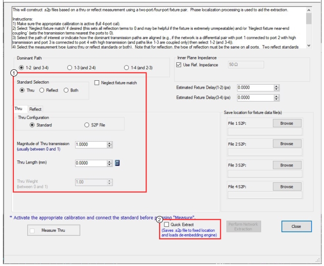
NETWORK EXTRACTION Dialog Box – Type F – Phase Localized (Option 21)
Full Name
Network Extraction [Extract Four 2-port Networks (Type F-Phase-Localized)]
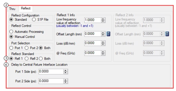
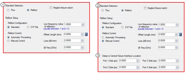
TYPE F – Phase Localized – Extraction Setup Variations
1. Checking Reflectand selecting Automatic Processing opens the dialog shown.
2. Checking Reflectand selecting Manual Control opens the dialog shown.
3. With Manual Control selected, Delay to Central Fixture Interface Location is enabled.
Instructions
This will construct .s4p files based on a thru or reflect measurement using a two-port/four-port fixture pair. Phase localization processing is used to aid the extraction.
To do this phase localization, the frequency list must be relatively uniform (no CW or log sweep and segmented sweep step sizes should not deviate more than 3% from the mean) and the range should be large enough that the total fixture length (ns)>5/(frequency range (GHz)). The frequency step should be small enough that the total fixture length (ns) < 0.3/(Frequency step (GHz)).
1. Make sure the appropriate calibration is active (a full 4-port cal for Type F).
2. Enter the file names where the output .s4p files will be stored. The Quick Extract option can be used instead: time stamped files will be saved to a predetermined hard disk location and the de-embedding engine will automatically load those files.
3. Select Neglect fixture match if needed (this sets all reflection terms to 0 and may be helpful if the fixture is extremely unrepeatable).
4. Select the path of interest or indicate how the dominant transmission paths are aligned (e.g., if the network is a differential pair with port 1 connected to port 2 with high transmission and port 3 is connected to port 4 with high transmission (and paths like 1-3 are coupled only) then select 1-2 (and 3-4)).
5. Select the measurement type (using Thru or Reflect standards). Note that for reflection, the type of reflection must be the same on all ports.
6. Define the standards being used (offset length, transmission or reflection magnitude, include the sign of reflection).
7. Enter an estimate of the network's electrical delay (both sides of the fixture pair). Entering 0 will activate the automatic length estimator. If using a reflect measurement, this can be further refined by selecting Manual Control where the fixture halves can be treated as asymmetric and only one side can be done if desired.
8. When all fields have been entered and proper connection of the standard or standards been made, click on Perform Network Extraction. If successful, files will automatically be saved and a confirmation dialog will appear.
10. If Quick Extract was not selected, after the .s4p files have been saved, go to Measurement | Edit Embed/De-embed | Edit Network configuration panel to recall the .s4p files and configure the network.
NETWORK EXTRACTION Dialog Box – Type G (No Option 21)
Full Name
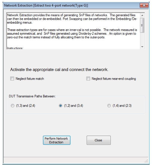
Network Extraction [Extract Two 4-port Networks (Type G)]
• MAIN | Calibration | CALIBRATION | De-embedding Tools | DEEMBED. TOOLS | Ntwk. Extraction | 4 Port Networks | NETWORK EXTRACTION (4-PORT NETWORKS) Dialog Box | Extract Two 4-Port Networks | Type G – Outer Cal Only Using Divide-By-Two Method | NETWORK EXTRACTION [EXTRACT FOUR 2-PORT NETWORKS (TYPE G)] Dialog Box
NETWORK EXTRACTION – EXTRACT TWO 4-PORT NETWORKS – TYPE G – 4-Port
Instructions
Network Extraction provides the means of generating SnP files of networks. The generated files can then be embedded or de-embedded. Port Swapping can be performed in the Embedding/De-embedding menus.
These extraction types are for cases where an inner-cal is not possible. The network measured is assumed symmetrical, and SnP files generated using Divide-by-2 schemes. An option is given to neglect fixture match terms instead of fully allocating them to the outer-ports.
Procedure:
1. Make sure the appropriate calibration is active.
2. Select Neglect fixture match if needed (this sets all reflection terms to 0 and may be helpful if the fixture is extremely unrepeatable).
3. Connect the network and select Perform Network Extraction.
4. If the extraction is successful, follow the prompt to save the generated SnP file(s).
5. After the .SnP files have been saved, go to Measurement | Edit Embed/De-embed | Edit Network configuration panel to recall the .SnP files and configure the network.
NETWORK EXTRACTION Dialog Box – Type G – Multi-Standards (Option 21)
Full Name
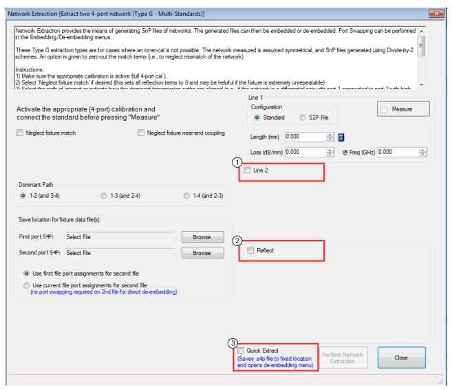
Network Extraction [Extract Two 4-port Networks (Type G – Multi-Standards)]
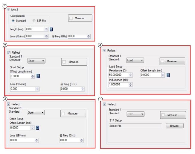
TYPE G– Multi-Standards – Extraction Setup Variations
1. Checking Line 2 Length box opens a dialog to adjust length.
2. Checking Reflect box and selecting Short from the dropdown opens the dialog as shown.
3. Checking Reflect box and selecting Open from the dropdown opens the dialog as shown.
4. Checking Reflect box and selecting Load from the dropdown opens the dialog as shown.
5. Checking Reflect box and selecting S1P from the dropdown opens the dialog as shown.
Instructions
Network Extraction provides the means of generating SnP files of networks. The generated files can then be embedded or de-embedded. Port Swapping can be performed in the Embedding/De-embedding menus.
These Type G extraction types are for cases where an inner-cal is not possible. The network measured is assumed symmetrical, and SnP files generated using Divide-by-2 schemes. An option is given to neglect fixture match terms (i.e., to neglect mismatch of the network).
1. Make sure the appropriate calibration is active (full 4-port cal for Type G).
2. Select Neglect fixture match if needed (this sets all reflection terms to 0 and may be helpful if the fixture is extremely unrepeatable).
3. Select the path of interest or indicate how the dominant transmission paths are aligned (e.g., if the network is a differential pair with port 1 connected to port 2 with high transmission and port 3 is connected to port 4 with high transmission, and the other paths like 1-3 and 2-3 are high loss, then select 1-2 (and 3-4)).
4. Select the number of standards to be used and their definitions. Line 1 is always required.
5. Connect each standard (or standards in the case of Reflect; all ports must have the Reflect connected simultaneously) before pressing Measure.
6. Enter the file names where the output (.s4p for Type G) files will be stored. The Quick Extract option can be used instead: files will be saved to a predetermined hard disk location and the de-embedding engine will automatically load those files.
7. When all fields have been entered and all standards measurements have been completed (all of the check boxes marked and the button fields have turned green), press Perform Network Extraction. If successful, a confirmation dialog will appear.
9. If Quick Extract was not selected, after the .s4p files have been saved, go to Measurement | Edit Embed/De-embed | Edit Network configuration panel to recall the .s4p files and configure the network.
NETWORK EXTRACTION Dialog Box – Type G – Phase Localized (Option 21)
Full Name
Network Extraction [Extract Two 4-port Networks (Type G – Phase-Localized)]
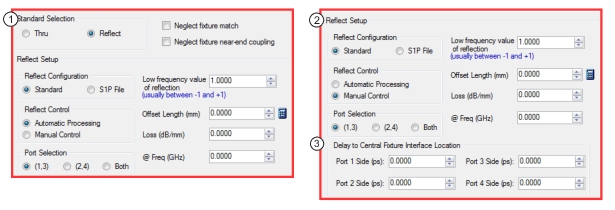
TYPE G – Phase Localized – Extraction Setup Variations
1. Checking Reflectand selecting Automatic Processing opens the dialog shown.
2. Checking Reflectand selecting Manual Control opens the dialog shown.
3. With Manual Control selected, Delay to Central Fixture Interface Location is enabled.
Description
This will construct .s4p files based on a thru or reflect measurement using a two-port/four-port fixture pair. Phase localization processing is used to aid the extraction.
To do this phase localization, the frequency list must be relatively uniform (no CW or log sweep and segmented sweep step sizes should not deviate more than 3% from the mean) and the range should be large enough that the total fixture length (ns) > 5/(frequency range (GHz)). The frequency step should be small enough that the total fixture length (ns) < 0.3/(Frequency step (GHz)).
Instructions
1. Make sure the appropriate calibration is active (full 4-port cal in general or a 2-port cal for a reflection-based extraction with a single-sided fixture).
2. Select ‘Neglect fixture match’ if desired (this sets all reflection terms to 0 and may be helpful if the fixture is extremely unrepeatable) and/or ‘Neglect fixture near-end coupling’ (sets the transmission terms nearest the ports to 0).
3. Select the path of interest or indicate how the dominant transmission paths are aligned (e.g., if the network is a differential pair with port 1 connected to port 2 with high transmission and port 3 is connected to port 4 with high transmission (and paths like 1-3 are coupled only) then select 1-2 (and 3-4)).
4. Select the measurement type (using thru or reflect standards or both). Note that for reflection, the type of reflection must be the same on all ports. Two reflect standards may be selected (and they must have different reflection coefficients) and for each of those measurement cycles, the same reflection standard should be on all ports. When ‘both’ (thru and reflect) is selected, there is also an available weighting factor with a range of 0 to 1. At 0, the reflect standard will dominate. At 1, the thru standard will dominate.
5. Define the standards being used (offset length, transmission or reflection magnitude, include the sign of reflection)
6. If reflect standards are selected, choose whether one or two will be used (the reflect standards must have different reflection coefficients). If ‘both’ (thru & reflect) is selected, only one reflect may be used. Two different reflection standards may be used but the same type would be connected to all ports at a given time.
7. Enter an estimate of the network's electrical delay (both sides of the fixture pair). Entering 0 will activate the automatic length estimator. If using a reflect measurement, this can be further refined using ‘Manual Control’ where the fixture halves can be treated as asymmetric and only one side can be done if desired.
8. Enter the file names and path where the output .s4p files will be stored. The Quick Extract option can be used instead: files will be saved to a predetermined hard disk location and the de-embedding engine will automatically load those files.
9. When all fields have been entered and proper connection of the standard(s) has(have) been made, click on the appropriate 'Measure' button. If 'both' types of standards were selected, then two measurements are required. If only reflect standards are being used but two are defined, then two measurement cycles will also be needed.
10. When measurement(s) is(are) complete, click on Perform Network Extraction. If successful, files will automatically be saved and a confirmation dialog will appear.
11. If Quick Extract was not selected, after the .s4p files have been saved, go to MEASUREMENT | Edit Embed/De-embed | Edit Network | EDIT EMBEDDING/DE-EMBEDDING configuration panel to recall the .s4p files and configure the network.
• A full term calibration needs to exist and be active.
Navigation
• MAIN | Calibration | CALIBRATION | De-embedding Tools | DEEMBED. TOOLS | Ntwk. Extraction | 4 Port Networks | NETWORK EXTRACTION (4-PORT NETWORKS) Dialog Box | Extract Two 4-Port Networks | Type G – Phase Localized High Cross Talk| NETWORK EXTRACTION [EXTRACT TWO 4-PORT NETWORKS (TYPE G – PHASE-LOCALIZED HIGH CROSSTALK)] Dialog Box
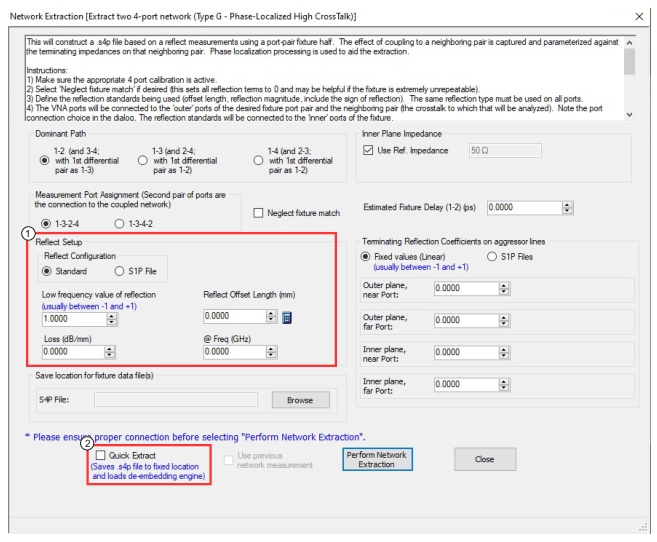
NETWORK EXTRACTION – EXTRACT TWO 4-PORT NETWORKS – TYPE G – Phase-Localized High Crosstalk – 4-Port
Description
This will construct a .s4p file based on a reflect measurement using a port-pair fixture half. The effect of coupling to a neighboring pair is captured and parameterized against the terminating impedances on that neighboring pair. Phase localization processing is used to aid the extraction.
To do this phase localization, the frequency list must be relatively uniform (no CW or log sweep and segmented sweep step sizes should not deviate more than 3% from the mean) and the range should be large enough that the total fixture length (ns) > 5/(frequency range (GHz)). The frequency step should be small enough that the total fixture length (ns) < 0.3/(Frequency step (GHz)).
Instructions
1. Make sure the appropriate 4 port calibration is active (full 4-port cal for Type G High Crosstalk).
2. Select Neglect fixture match if needed (this sets all reflection terms to 0 and may be helpful if the fixture is extremely unrepeatable).
3. Define the reflection standards being used (offset length, reflection magnitude, include the sign of reflection). The same reflection type must be used on all ports.
4. The VNA ports will be connected to the ‘outer’ ports of the desired fixture port pair and the neighboring pair (the crosstalk to which will be analyzed). Note the port connection choice in the dialog. The reflection standards will be connected to the ‘inner’ ports of the fixture.
5. Enter an estimate of the network’s electrical delay (both sides of the fixture pair). Entering 0 will activate the automatic length estimator.
6. Enter the terminating reflection coefficients (either frequency-independent scalars or .s2p files) for the neighboring pair (as it will be used in practice).
7. Enter the file name and path where the output .s4p file will be stored. The Quick Extract option can be used instead; time-stamped files will be saved to a predetermined hard disk location and the de-embedding engine will automatically load those files. Remember to keep track of available disk space. The output .s4p file will be for the desired port pair using the defined terminations on the neighboring pair. Internally, a .s8p is generated that generically defines the dual network. This file is saved so a new .s4p file can be generated later using new neighboring pair terminations (see Use Previous Measurement checkbox).
8. When all fields have been entered and proper connection of the standard(s) has (have) been made, click on Perform Network Extraction. If successful, files will automatically be saved and a confirmation dialog will appear.
10. If Quick Extract was not selected, after the .s4p file has been saved, go to the MEASUREMENT | EDIT EMBED/DE-EMBED / EDIT NETWORK CONFIGURATION dialog to recall the .s4p file and configure the network.
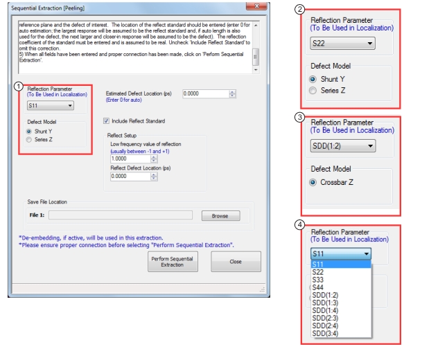
Sequential Extraction will construct a .s2p or .s4p file based on a localization of the selected parameter to isolate a given defect. This process can be used to sequentially de-embed and identify additional defects.
3. Reflection Parameter selected is SDD(1:2), Mixed Mode Selection Defect Model is Crossbar Z, file would be .s4p
4. Available selections for a full 4-port calibration
Description
Sequential Extraction will construct a .s2p or .s4p file based on a model of an isolated defect (treated as lumped). This process can be used to sequentially de-embed and identify additional defects.
Notes:
• The Reflection Parameter selection is dynamic and will be based on active cal settings.
Note: If no active cal is in place or cal is off, the Reflection Parameter drop down list will be disabled with a note indicating requirement.
• If the Reflection Parameter is switched between Standard and Mixed, the file name will be cleared. The Browse button on file name will bring up appropriate filter (.s2p or .s4p) based on current selected reflect parameter.
• When Perform Sequential Extraction is selected, measurement will be taken and the processing of the mixed mode will occur internally.
Instructions
1. Select the Reflection Parameter to be used in the localization. Note: If no active cal is in place or cal is off, the Reflection Parameter drop down list will be disabled with a note indicating requirement.
2. Enter an Estimated Defect Location. This is only used to help with root selection and need not be extremely accurate. Entering 0 will activate the automatic length estimator.
3. Select the Defect Model (shunt admittance Y, series impedance Z, or in the case of differential parameters, a crossbar impedance).
4. Select Include Reflect Standard to include the reflect standard to help compensate for loss between the reference plane and the defect of interest. The location of the reflect standard should be entered (enter 0 for auto estimation; the largest response will be assumed to be the reflect standard and, if auto length is also used for the defect, the next larger and closer-in response will be assumed to be the defect). The reflection coefficient of the standard must be entered and is assumed to be real. Uncheck Include Reflect Standard to omit this correction.
5. When all fields have been entered and proper connection has been made, click on Perform Sequential Extraction.
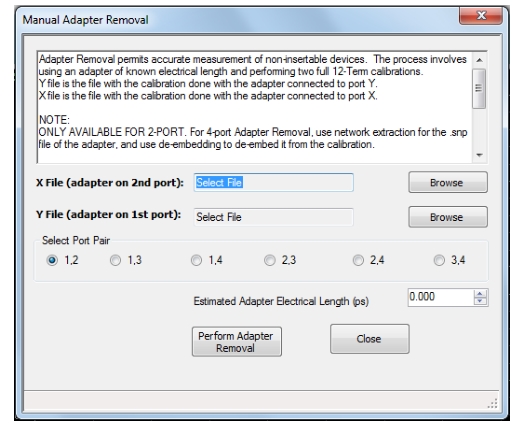
Use manual adapter removal to extract the electrical behavior of an adapter after a successful calibration procedure. This is especially useful when the DUT configuration is not entirely compatible with common calibration procedures such as having different connectors at each end.
Adapter removal permits accurate measurement of non-insertable devices. The process involves using an adapter of known electrical length and performing two full 12-term calibrations. In the procedure below:
• The Y file is the file with the calibration when the adapter connected to Port 1.
• The X file is the file with the calibration when the adapter connected to Port 2.
Note
ONLY AVAILABLE FOR 2-PORT.
For 4-port Adapter Removal, use network extraction for the SnP file of the adapter, and use de-embedding to de-embed it from the calibration.
Procedure
Select the port pair to be used.
1. Connect the adapter to Port X where X signifies any port. Perform a full 12-term calibration using Y' and Y as the test ports and store calibration to disk.
2. Connect the adapter to Port Y where Y signifies any port that is not X. Perform a full 12-term calibration using X and X' as the test ports and store calibration to disk.
3. Call up the X and Y files.
4. Input the estimated adapter electrical length in picoseconds (ps).
5. Select Perform Adapter Removal to remove adapter.
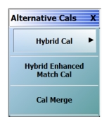
ALTERNATIVE CALS Menu – 4-Port VNAs
Use the ALTERNATIVE CALS menu to hybridize and merge calibrations.
• MAIN | Calibration | CALIBRATION | Alternative Cals| ALTERNATIVE CALS
CAL KIT/AUTOCAL Menu – 2-Port VNAs
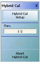
Hybrid Cal
Hybrid calibration takes either up to four 1-port cals and hybridizes them into a 2-port, 3-port, or 4-port cal, or takes two 2-port cals and hybridizes them into one 4-port cal.
Hybrid Enhanced Match Cal (Disabled when 4-Port Test Set Connected
Available only on 2-port instruments with Option 7, Receiver Offset (disabled when Option 7 is not installed and when a 4-port test set is connected). Allows a version of hybrid calibrations (mentioned above) for frequency converting devices (mixers) to take two enhanced match calibrations and hybridize them into a new enhanced match calibration with the input media of the first calibration and the output media of the second calibration. This allows a mixed-media calibration for a device that may have coaxial and waveguide connections.
Cal Merge
Cal Merge allows merging two calibration files into a single file where the calibrations can use different methods at different frequencies. The calibrations must be of the same calibration type. Select displays the CAL MERGE dialog box.
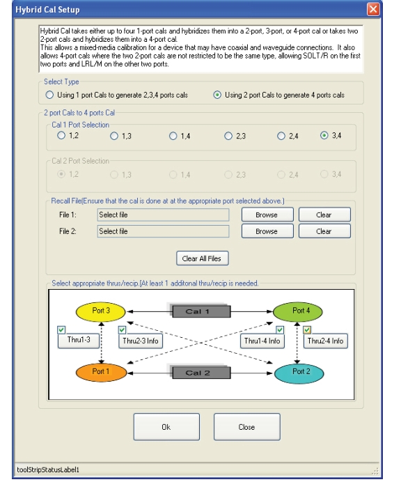
• MAIN | Calibration | CALIBRATION | Alternative Cals | ALTERNATIVE CALS | Hybrid Cal | HYBRID CAL | Hybrid Cal Setup | HYBRID CAL SETUP Dialog Box
HYBRID CAL (CALIBRATION) Dialog Box – 4-Port VNAs
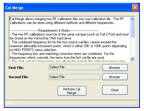
CAL MERGE Dialog Box – 4-Port VNAs
Calibration merge allows merging two calibration files into a single file where the prior calibrations can use different methods (such as SOLT and SSLT) at different frequencies. The calibrations must be the same calibration type (such as Full 1 Port) and be available on the instrument hard drive. Calibration merge has other requirements (described below) as to the number of points, start and stop frequencies, and front panel settings.
• MAIN | Calibration | CALIBRATION | Alternative Cals | ALTERNATIVE CALS | Cal Merge | CAL MERGE Dialog Box
CAL MERGE Dialog Box
Instructions
Cal Merge allows merging two RF calibration files into one calibration file. The RF calibrations can be done using different methods and different frequencies.
Requirements and Notes
• The two RF calibrations must be of the same calibration type (such as Full 2 Port) and must be stored on the VectorStar VNA hard drive.
• The combined frequency list for the two source cal files cannot exceed the maximum allowable instrument points, which is either 25K or 100K points, depending on MAX POINTS menu selection.
• The frequency lists and matching correction terms are combined. For the frequencies which coincide, the terms from the first cal file are used.
• The start and stop frequencies are adjusted to include the entire frequency range provided by the two cal files.
• The first cal file provides all other front panel setup configuration information.
• Since Calibration Merge can result in non-discrete step size, the cal merge file sweep type is set to Frequency-Based Segmented Sweep.
Procedure
1. 1) Select Browse to select the appropriate cal files. For example, select a file such as calfile1.chx for the first file and calfile2.chx for the second file.
2. Select Perform Cal Merge to perform the merge of the frequency lists and matching correction terms.
3. For best practices it is recommend saving the resultant Cal Merge file, but a save is not required.