7. CALIBRATION Menu – Appearance and button availability changes for Noise Figure operation. Button provides direct access to the NOISE CALIBRATION Dialog Box described above. When in Noise Figure mode, path via CALIBRATION menu is: MAIN | Calibration | CALIBRATION | Perform Noise Calibration.
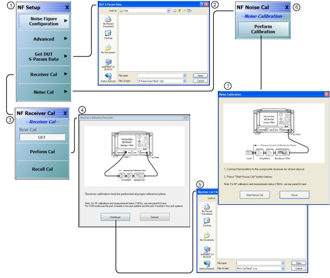
Select displays the DUT S-PARAM DATA dialog box. Once opened, navigate to the location of the stored DUT S-Parameter Data file. Once found, select the Open button to retrieve the file. The DUT data file must be stored and available before starting noise figure measurements.
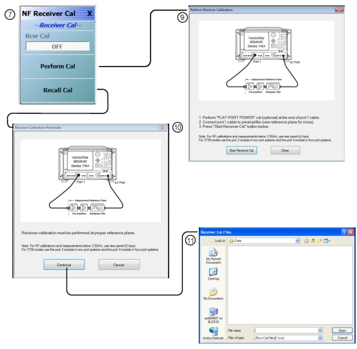
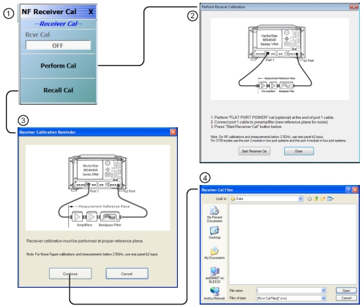
NF Receiver Calibration
Select displays the NF RECEIVER CAL menu (see NF SETUP Menu – Receiver Cal). Once open, select RECALL CAL and follow the steps below. (One can also perform a receiver calibration at this point instead of recalling it by selecting the PERFORM button and connecting port 1 to the input of the composite receiver).
Recall Calibration
Select displays the RECEIVER CALIBRATION REMINDER dialog box with the reminders below. Select Continue to proceed. Select Cancel to return to the NF SETUP menu.
• Receiver calibration must be performed at proper reference plane.
• For noise figure calibrations and measurement below 2.5 GHz, use the rear panel b2 input.
1. Select Continue to proceed.
2. The RECEIVER CAL FILES recall dialog box appears.
3. Navigate to the location of the previously stored receiver calibration RCVR file.
4. Select Open.
5. Return to the NF SETUP menu.
NF Noise Calibration
Select displays the NF NOISE CAL menu. Once open, select PERFORM CALIBRATION and follow the steps below.
Perform Calibration
Select displays the NOISE CALIBRATION dialog box. Once open, follow the procedure below to calibrate the noise:
1. Connect the termination to the preamplifier at the reference plane of the noise figure measurement. The dialog box figure shows the placement of the required components.
2. Select the Start Noise Cal button on the dialog box to start the calibration.
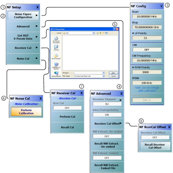
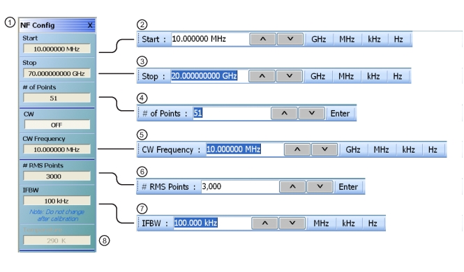
1. NF CONFIG menu – Related button field toolbars shown to the right.
2. Start Frequency field toolbar.
3. Stop Frequency field toolbar.
4. # (Number) of Points field toolbar.
5. CW Frequency field toolbar.
6. # of RMS Points field toolbar.
7. IFBW (Intermediate Frequency Bandwidth) Frequency field toolbar – Do not change the IFBW setting after calibration.
8. Temperature K – Read-only display field button.
Start
Select displays the Start frequency field toolbar to provide input for the start frequency in GHz, MHz, kHz, or Hz.
Stop
Select displays the Stop frequency field toolbar to provide input for the stop frequency in GHz, MHz, kHz, or Hz.
# of Points
Number of Points. Select displays the # of Points field toolbar to provide input for the number of sweep points.
CW
Continuous Wave Frequency. Select displays the CW field toolbar to provide input for the CW frequency in GHz, MHz, kHz, or Hz.
# RMS Points
Number of Root Mean Square Points. Select displays the # RMS Points field toolbar to provide input for the number of RMS measurement points per sweep point set above. For example, if the sweep points are set to 51, and the RMS points are set to 3,000, the total measurement points are 51 × 3,000 = 153,000.
IFBW
Intermediate Frequency Bandwidth. Select displays the IFBW field toolbar to provide input for the IFBW frequency in MHz, kHz, or Hz.
Note
Do not change the IFBW setting after calibration.
Temperature K
Temperature Kelvin. Read-only display of the IEEE default temperature of 290 K. For reference:
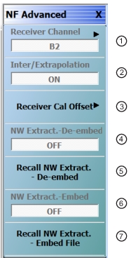
1. Receiver Channel: Read-only field display. Shows the receiver channel as B2.
2. Inter/Extrapolation: Calibration Interpolation and Extrapolation Mode. Read-only display. This display indicates that the VNA calibration interpolation and extrapolation mode is ON.
3. Receiver Cal Offset: Opens the NF RCVRCALOFFSET menu. After loading the receiver cal offset file (.txt), a CheckBox (as checked) will be shown to indicate the successful file load. Also, the menu item “Receiver Cal Offset” toggle will be enabled and the status will be changed to ON.
4. NW Extract.–De-embed: Read-only field display. Shows the NW Extract–De-embed status.
5. Recall NW Extract.–De-embed File: Opens Select S2P FIle for Network DeEmbedding dialog box, which is used to select an s2p file.
6. NW Extract.–Embed: Shows the NW Extract–Embed status. When ON, the user is able to toggle the Network Extraction status to ON/OFF by clicking this menu item.
7. Recall NW Extract.–Embed File: Opens Select S2P FIle for Network Embedding dialog box, which is used to select an s2p file. The selected s2p file is validated and if found valid, the embedding operation will be performed with respect to the selected s2p file. A CheckBox (as checked) will be shown to indicate the file loaded successfully. Also the menu item “NW Extraction. Embed” will be enabled and the status will be changed to ON.
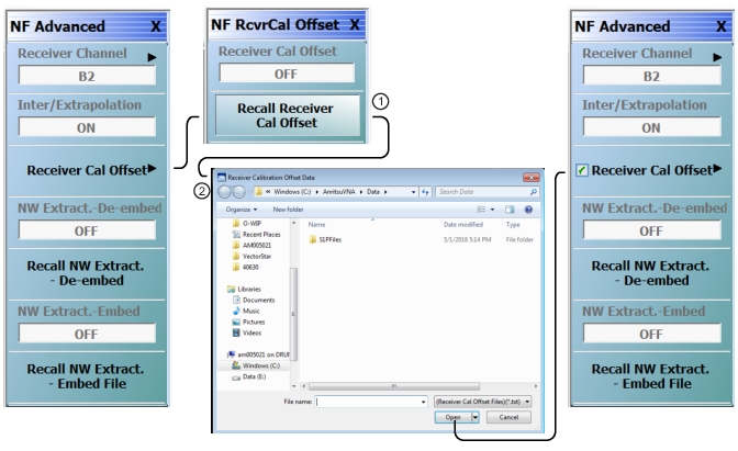
NF ADVANCED Menu – Receiver Cal Offset
Full Name
Noise Figure Advanced Configuration Menu Receiver Cal Offset
Prerequisites
• Option 41 is installed on the VNA.
• The non-compressed DUT S-Parameter Data file has been stored and is available on the VNA with the filename extension .sp2 or .txt.
• The APPLICATION menu mode is set to Noise Figure mode.
NF ADVANCED Menu: NF RCVRCAL OFFSET Menu – Option 41
1. Recall Receiver Cal Offset: Opens Receiver Calibration Offset Data dialog box. After loading the receiver cal offset file (.txt), a CheckBox (as checked) will be shown to indicate the successful file load. Also, the menu item “Receiver Cal Offset” will be enabled and the status will be changed to ON.