 |
|
 |
 |
 |
 |
 |
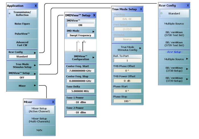
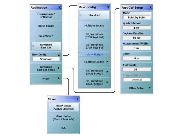
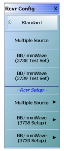 | Standard Sets the Standard receiver configuration and de-selects all other receiver configurations and their respective selection buttons. Multiple Source Requires the installation of Option 7 – Receiver Offset. Select sets the Multiple Source receiver configuration and de-selects all other receiver configurations and their respective selection buttons. If selected, use the Rcvr Setup section of the menu (Multiple Source setup) described below to configure the multiple sources, including external sources. For detailed information, see: mmWave (3738 Test Set) This button name appears on MS4642B, 44B, or 45B VNAs with Option 7. Sets the receiver configuration as mmWave (3738 Test Set). Use the Rcvr Setup section of the menu (mmWave (3738 Test Set) to set up this receiver configuration. BB/mmWave (3738 Test Set) This button name (shown in screen shot) appears on MS4647B VNAs with Option 7. Sets the receiver configuration as BB/mmWave (3738 Test Set). Use the Rcvr Setup section of the menu (BB/mmWave (3738 Test Set) to set up this receiver configuration. mmWave (3739 Test Set) This button name appears on MS4642B, 44B, or 45B VNAs with Option 7 and a compatible Option 8x. Sets the receiver configuration as mmWave (3739 Test Set). Use the Rcvr Setup section of the menu (mmWave (3739 Test Set) to set up this receiver configuration. (Continued) |
BB/mmWave (3739 Test Set) This button name (shown in screen shot) appears on MS4647B VNAs with Option 7 and a compatible Option 8x. Sets the receiver configuration as BB/mmWave (3739 Test Set). Use the Rcvr Setup section of the menu (mmWave (3739 Test Set) to set up this receiver configuration. Receiver Setup Section: Multiple Source Setup Available on all VNAs. Select displays the MULTIPLE SOURCE SETUP menu. Use this button if the Multiple Source Receiver Configuration was selected above. mmWave (3738 Setup) Only available on MS4642B, 44B, or 45B VNAs with Option 7. Select displays the 3738 SETUP menu. Use this button for configuration if the mmWave (3738 Test Set) was selected above. BB/mmWave (3738 Setup) Available on MS4647B VNAs with Option 7. Select displays the 3738 SETUP menu. Use this button for configuration if the BB/mmWave (3738 Test Set) was selected above. mmWave (3739 Setup) Available on MS4642B, 44B, or 45B VNAs with Option 7 and a compatible Option 8x. Select displays the 3739 SETUP menu. Use this button for configuration if the mmWave (3739 Test Set) was selected above. BB/mmWave (3739 Setup) Available on MS4647B VNAs with Option 7 and a compatible Option 8x. Select displays the 3739 SETUP menu. Use this button for configuration if the BB/mmWave (3739 Test Set) was selected above. |
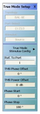 | For detailed information, see DifferentialView™ (True Mode Stimulus) Topology Identifies the stimulus configuration that is set in the True Mode Stimulus Configuration dialog box. The following topologies and port assignments are available in 4-port instruments: Port Select Identifies the port selection that is set in the True Mode Stimulus Configuration dialog box. Differential port pair selection of (1:2) or (3:4) is not valid when in TMS mode. Stimulus Identifies the stimulus that is set in the True Mode Stimulus Configuration dialog box. True Mode Stimulus Config Opens the DifferentialView – True Mode Stimulus dialog to select and configure a differential stimulus measurement. Ref. To Port Opens a dialog to select the frequency and phase offset reference port (can be any port 1 through 4). TMS Phase Offset Sets the fixed phase offset that is applied to the true differential drive for situations that require stimulus compensation. TMS Power Offset Sets the fixed power offset (in dB) that is applied to the true differential drive for situations that require stimulus compensation. Phase Start Sets the starting phase offset (± 3600°) in phase sweep configuration (CW only). Phase Stop Sets the starting phase offset (± 3600°) in phase sweep configuration (CW only). |
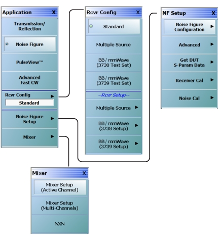
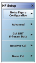 | For detailed information, see Noise Figure (Option 41) Noise Figure Configuration Select displays the NF CONFIG menu. Advanced Select displays the NF ADVANCED menu. Get DUT S-Param Data Select displays the DUT S-PARAM DATA dialog box. Receiver Cal Select displays the NF RECEIVER CAL menu. Noise Cal Select displays the NF NOISE CAL menu. |
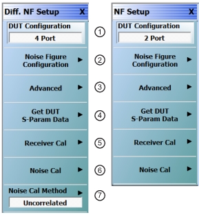 | |
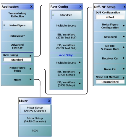
For detailed information, see Differential Noise Figure (Option 48) 1. DUT Configuration Selects 2-port or 4-port DUT configuration. 2. Noise Figure Configuration Select displays the NF CONFIG menu. 3. Advanced Select displays the NF ADVANCED menu. 4. Get DUT S-Param Data Select displays the DUT S-PARAM DATA dialog box. 5. Receiver Cal Select displays the NF RECEIVER CAL menu. 6. Noise Cal Select displays the NF NOISE CAL menu. 7. Noise Cal Method (Only available for 4-Port DUT Configuration) Select displays the DIFF. NF METHODS menu. |
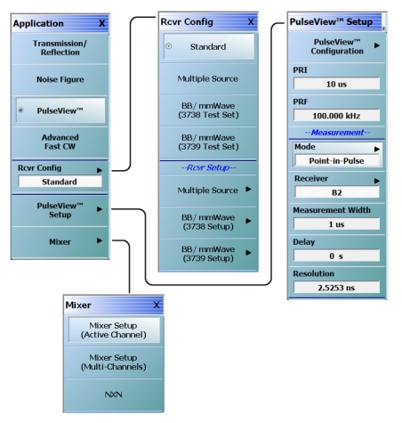
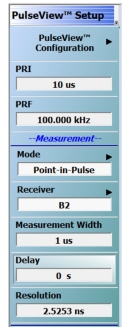 | For detailed information, see PulseView™ PulseView Configuration Opens the PulseView Configuration Dialog Box. PRI Pulse Repetition Interval – Sets the primary clock synch pulse period in units of time. PRF Pulse Repetition Frequency – Sets the primary clock synch pulse repetition rate in units of hertz. Mode Opens the Pulse Mode menu to select the pulse mode. # of Points Sets the number of measurement points from the Start to the Stop time settings. # of Pulses Sets the number of pulse measurements to acquire. Receiver Selects a receiver channel to configure. Measurement Width Sets the measurement width time (aperture). Start Time Time to wait relative to T0 before measuring a pulse. Stop Time Time relative to T0 at which the measurement should stop. Delay Time relative to T0 before starting the measurement. Resolution Defines the minimum time resolution. |
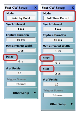 | For detailed information on this application menu, see Advanced Fast CW Mode Toggles the mode between Point by Point and Full Time Record. Note that depending on the mode selected, the time parameters change from Delay (for PBP) to Start/Stop (for FTR). Synch Interval Synchronization Interval – Sets the synch interval in units of time. Capture Duration Sets the amount of data (in terms of time) that will be collected. Measurement Width Sets the width of the time window that will be used in transforming to the frequency domain. The wider the measurement width, the lower the effective processing IF bandwidth. Delay (Point by Point mode only) Sets the delay time from the synch interval beginning (whether that is internally or externally generated) to the time when a measured width-worth of data will be analyzed. Start Time (Full Time Record mode only) Sets the beginning of the portion of the collected time record that will be analyzed. Stop Time (Full Time Record mode only) Sets the end of the portion of the time record that will be analyzed. |
# of Points Sets the number of measurement points from the Start to the Stop time settings. Trigger Source Displays the trigger source that is selected from Other Setup (Addl.FCW Setup) menu. This becomes active as a manual trigger button when the Trigger source is set to Manual. Other Setup Select opens the Addl.FCW Setup menu for more Fast CW setup parameters. |
Note | In the Application menu, IMDView Setup button is disabled unless Option 44 is installed on the VNA, and Transmission/Reflection mode is activated. IMDView is also disabled in 4-port systems and if in 100K-point mode. |
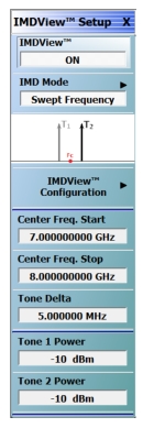 | Note: The IMDVIEW SETUP menu selections vary depending on the IMD Mode selection. For detailed information on the IMDVIEW SETUP menu, see IMDView™ IMDView ON/OFF Toggles the IMDView Application on or off. IMD Mode Opens the IMD MODE SELECT menu. Choices are Swept Frequency or SpectrumView. IMDView Configuration Opens the IMDVIEW CONFIGURATION dialog box. Center Frequency Start Sets the center frequency (fc) start. Center Frequency Stop Sets the center frequency (fc) stop. Tone Delta Sets the spacing between the main tones. In other literature, it is sometimes called “offset” or “tone spacing”. Tone 1 Power Sets the IMD measurement Tone 1 power level. Tone 2 Power Sets the IMD measurement Tone 2 power level. |
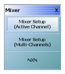 | Mixer Setup (Active Channel) Displays the single channel version of the mixer setup, the MIXER SETUP [SWEEP TYPE] dialog boxes. The setup allows setting the sweep type, the port correspondence to RF and IF, and the signal source for the LO. There are separate setup configurations for frequency-based sweep and power-based sweep. Note: Mixer Setup (Active Channel) button is active in 2-Port mode. Mixer Setup (Multi-Channels) Displays the MIXER SETUP CONFIGURATION dialog boxes. The mixer setup dialogs provide setup guidance for different mixer types, and supports measurement of various parameters on different channels. Once the mixer configuration and measurement requirements are input, the system responds with the necessary calibrations required. The mixer measurement configuration can be saved and recalled. Note: Mixer Setup (Multi-Channels) is active in 2-Port mode. NxN Select displays the NXN SOLUTION USING S2P FILES dialog box. • NxN |
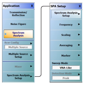
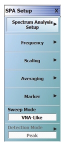 VNA-like Mode VNA-like Mode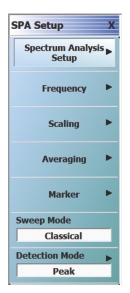 Classical Mode Classical Mode | For detailed information, see Spectrum Analysis Spectrum Analysis Setup Select displays the SPECTRUM ANALYSIS SETUP dialog. Frequency Select displays the FREQUENCY menu. Scaling Select displays the SCALE menu. Averaging Select displays the AVERAGING menu. Marker Select displays the MARKERS [1] menu. Sweep Mode Select toggles between VNA-like mode and Classical mode. Detection Mode Select displays the DETECTION MODE menu. |