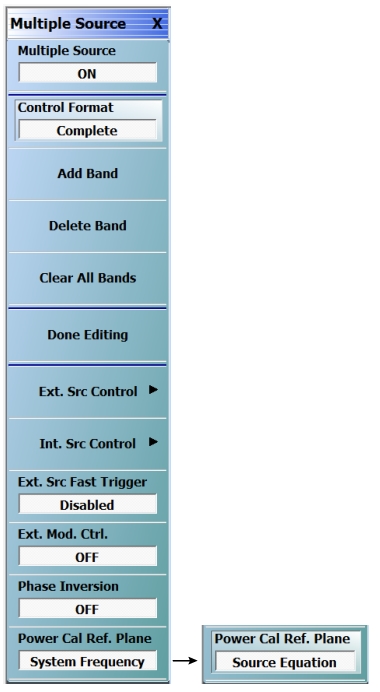
When the MULTIPLE SOURCE menu is selected, the Multiple Source Tableau Dialog appears at the bottom of the main display area.
Multiple Source (Off/On)
Select toggles multiple source capability to off or on and sets the Rcvr Config to Multiple Source.
Note
For multiple source to take effect, the “Done Editing” button should be selected. If you are in the middle of defining the bands and have not selected “Done Editing”, the band in effect will be the previous band and not the one currently being defined.
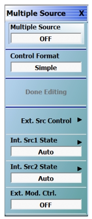
Control Format
Present Simple or Complete Multiple Source menu.
Add Band
Select adds a frequency band to the multiple source tableau at the bottom of the display.
If no changes have been made to the frequency band settings, this button is unavailable.
Once changes are made, the button becomes available.
When all changes are complete, select the Done Editing button to apply the frequency band changes (additions, edits, and deletions) to the current running measurement and its attached test sets and modules.
After the change have been applied, the button again becomes unavailable.
If the button is not selected, the changes are not applied to the instrument.
Select displays the INT. SRC CONTROL menu. This menu is not available when any of the TMS modes are active. When TMS mode is active, the internal sources are controlled by the TMS mode settings. Refer to DifferentialView™ (True Mode Stimulus) for information on TMS configuration.
The button displays the current broadband setting as either OFF, mmWave [3738], mmWave [3739], Broadband to 125 GHz, Broadband to 145 GHz, E-Band 56 GHz to 96 GHz, or W-Band 65 GHz to 110 GHz.
Select displays the EXTERNAL MODULE CTRL dialog box. The dialog box allows the module type to be set as OFF, mmWave [3738], mmWave [3739], Broadband to 125 GHz, Broadband to 145 GHz, E-Band 56 GHz to 96 GHz, or W-Band 65 GHz to 110 GHz which also depends on the connected equipment and installed options. If any configuration other than OFF is selected, additional configuration parameters are available for each defined band. The dialog box content depends on the broadband mode and the number of bands selected. Sample dialogs for some configurations are shown below:
Select toggles the phase inversion function off and on.
Power Cal Ref. Plane
Select toggles the Power Cal Reference Plane between System Frequency and Source Equation.
For a given multiple source setup, there are a number of different physical configurations that exist and the user may desire to perform power calibrations at different frequency reference planes.
For example, if Source 1=(1/4)*(f) and the DUT is a multiplier, one would want to power calibrate the source at the (1/4)*(f) plane. With the same equation but with the VNA source driving a mmWave module used for amplifier measurements, one may instead want to power calibrate the source at the f plane.
Thus some flexibility in what plane the user power calibration routine uses (in terms of what power meters the system looks for and what frequency is programed into the power meter) is desirable. This switch defines that reference plane.
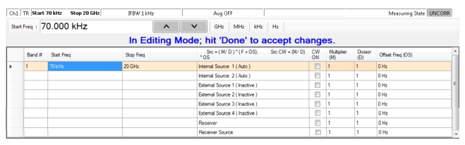
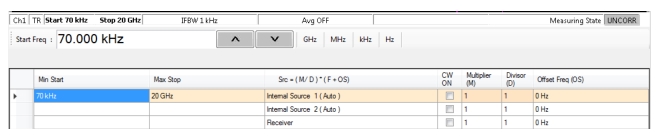
Multiple Source Tableau Dialog
The multiple source tableau is available at the bottom of the screen when the MULTIPLE SOURCE menu is selected. Typical Complete and Simple examples are shown below.
MULTIPLE SOURCE TABLEAU Dialog – Complete Example
MULTIPLE SOURCE TABLEAU Dialog – Simple Example
Band Tableau Controls: Complete
Bands are added by selecting the Add Band button on the MULTIPLE SOURCE menu. Up to 50 Bands can be added. Each band can be defined for any combination of the following sources:
• Internal Source 1
• Internal Source 2 (Option 31)
• External Source 1
• External Source 2
• External Source 3
• External Source 4
• Receiver
• Receiver Source
Band Tableau Controls: Simple
Bands are added by selecting the Add Band button on the MULTIPLE SOURCE menu. Up to 50 Bands can be added. Each band can be defined for any combination of the following sources:
• Internal Source 1
• Internal Source 2 (Option 31)
• External Source 1
• External Source 2
• External Source 3
• External Source 4
• Receiver
• Receiver Source
General Operation
The following general operation notes and requirements apply:
• Tabular field data can be entered in any sequence.
• If invalid data is entered, a warning icon appears in the left margin of the table. Selecting the Done Editing button with invalid data results in a warning dialog.
• Read-only tabular elements are distinguished from editable contents.
• Table focus remains on the last added/ deleted band.
• Data is not applied to the instrument and its attached equipment until the Done Editing button is selected. When successful, the button again becomes unavailable.
CW OFF
Each source is defaulted as CW off. A check box can be selected to enable CW for each source. If CW is not selected, the source equation is:
Where:
• M = Multiplier
• D = Divisor
• F = Frequency in user-defined units of Hz, kHz, MHz, or GHz. This is the current instrument frequency within the band being defined.
• OS = Offset frequency in Hertz
CW ON
If CW is selected, the source equation is:
Where:
• M = Multiplier
• D = Divisor
• OS = Offset frequency in Hertz
Band Management
Band management is done by using the Add Band, Delete Band, and Clear All Bands button. After all bands are configured, select Done Editing button to apply the setting to the instrument and its attached equipment.
Saving/Recalling Band Configurations
A multiple source band configuration can be saved by using MENU BAR | File | Save Setup. On the SAVE SETUP dialog box, the setup can be saved as a:
• Active Channel Setup and Calibration CHX file
• Active Channel Setup STX file
• All Channel Setup and Calibration CHA file
• All Channel Setup STA file
Recall previously saved setups by using MENU BAR | File | Recall Setup.
File operations are duplicated on the FILE menu at MAIN | File | FILE.
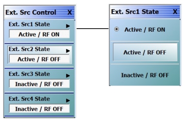
• Inactive / RF OFF button (Default if source is connected.)
In this section, these buttons are referred to as the External Source State buttons.
External Source State Buttons Inactive and Unavailable
If the External Source State buttons are Inactive and Unavailable (grayed out), either no external sources are connected to the instrument, or the external sources have different GPIB addresses from those set on the VNA instrument. Once one or more external sources are connected with matching GPIB addresses, the buttons change to Inactive and Available (not grayed out).
Connecting an External Source
Connect from one (1) to four (4) external sources via the rear panel Dedicated GPIB Port D-24 (f) Connector.
This GPIB port is used when the VNA instrument controls external instruments such as power meters, frequency counters, and in this case, external sources. Up to four (4) external sources can be connected to the instrument.
Note that each external instrument and the VNA must have a unique GPIB address with no duplicates. The factory-default GPIB addresses for the four external sources and other likely external instruments are:
• External Source 1 = GPIB Address 4
• External Source 2 = GPIB Address 5
• External Source 3 = GPIB Address 2
• External Source 4 = GPIB Address 3
• Power Meter = GPIB Address 13
• W-Band Power Meter = GPIB Address 15
• Frequency Counter = GPIB Address 7
• MN469xB/C Series Multiport Test Set = GPIB Address 16
• Frequency Counter = GPIB Address 7
• The VNA Instrument itself = GPIB Address 6
The default addresses for external sources can be changed at the EXT. SRC. ADDR. (EXTERNAL SOURCE ADDRESS) menu
• MAIN | System | SYSTEM | Remote Interface | REMOTE INTER. | Ext. Sources | EXT. SRC. ADDR.
The default addresses for the instrument itself, the external power meter, and the external frequency counter can be changed at the REMOTE INTER. menu.
• MAIN | System | SYSTEM | Remote Interface | REMOTE INTER.
• Only Anritsu external sources such as the MG3696A Signal Generator or the MS3695B Signal Generator can be connected.
• The external sources must be off during the connection process. The VNA instrument can be running.
• Connect the GPIB cables between the instrument and the external sources.
Note
Best practices recommend no more than two (2) GPIB cable connectors be connected to any one GPIB port. Once connected, do not bend the connectors as this might damage the instrument Dedicated GPIB Port Connector.
Matching GPIB Addresses Between the VNA and the External Source
The GPIB addresses set on the VNA instrument must match those set on each external source.
If the GPIB addresses set on the VNA match those on the external source, the appropriate External Source State button should change from unavailable (grayed out) to available. Once an External Source State button is available, it can be used to toggle the external source between Inactive and Active.
Manual Refresh Required for the EXT. SRC. CONTROL Menu
Note that the EXT. SRC. CONTROL menu does not refresh itself if address changes are made in any of the external sources. If in doubt about the state of connected external sources, click the Back button at the bottom of the display, and then re-enter the menu.
• For example, if a single external source with a GPIB address of 4 is connected to the VNA, the (Ext. Src1) State [Inactive/Active] button is available and can toggle the source as Active or Inactive.
• The user changes the GPIB address of the external source from 4 to 5.
• The current EXT. SRC. CONTROL menu will still show the (Ext. Src1) State [Inactive/Active] button as available.
• To verify the currently connected external sources, select Back to exit the EXT. SRC ADDR. menu to the REMOTE INTER. menu and then select again the Ext. Sources button to re-enter the EXT. SRC. CONTROL menu.
• In this example, the EXT. SRC. CONTROL menu will now show:
• The (Ext. Src1) State [Inactive/Active] button as unavailable
• The (Ext. Src2) State [Inactive/Active] button as available
All external source control buttons follow this behavior.
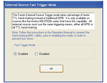
EXTERNAL SOURCE FAST TRIGGER MODE Dialog Box
Previous
This menu can be accessed from multiple locations.
This Fast External Source Trigger mode takes advantage of faster TTL hand-shaking instead of traditional GPIB. It is only available on sources such as the Anritsu MG37020x Series Signal Generators that have this capability. All external sources must use the same triggering means, either all GPIB or all TTL hand-shaking.
Note
Ensure that the BNC cable is connected properly before enabling this mode to prevent source lock errors. The length of the BNC cables can vary, while the BNC T-Connectors should all be the same type from the same manufacturer. Select OK when done.
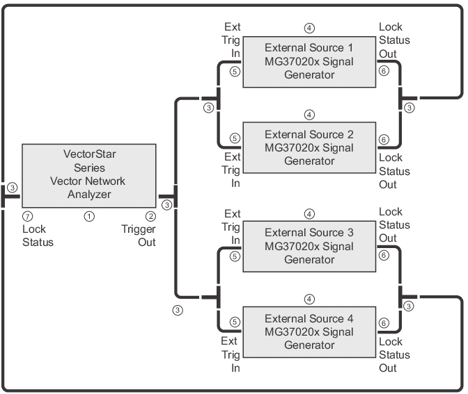
In the Fast Trigger Mode area, select Enabled or Disabled, and then select OK. The general configuration is shown in the figure below.
External Source Fast Trigger BNC Cable Connections
3. BNC T-Connectors – For this application, the best practice recommendation is to use the same model number BNC T-connectors from the same manufacturer. The BNC cables do not need to be identical length nor do they need to be from the same manufacturer.
4. Anritsu MG3702xX Signal Generators – Up to four (4) signal generators can be connected.
• This menu is not available when any of the TMS modes are active. When TMS mode is active, the internal sources are controlled by the TMS mode settings. Refer to DifferentialView™ (True Mode Stimulus) for information on TMS configuration.
Navigation
• MAIN | Application | APPLICATION | Rcvr Config | RCVR CONFIG | Multiple Source | MULTIPLE SOURCE | Int. Src Control | INT. SRC CONTROL
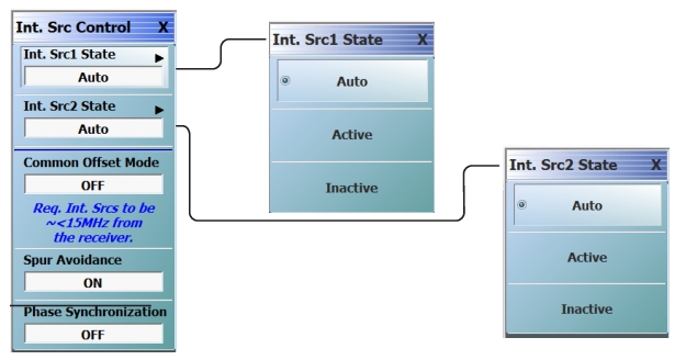
INT. SRC CONTROL (INTERNAL SOURCE CONTROL) Menu
INT. SRC CONTROL Menu Note
Initiates the dual source drive at both ports. As shown, the setup includes identification of two internal sources that can be set to “Auto” or “Manual” mode. In “Manual” mode, they are either “Active” (always on) or “Inactive” (always off). The setting of the internal sources is controlled via the Multiple Source Tableau Dialog.
INT. SRC CONTROL Menu Note (when IMDView is active)
When IMDView is active, any internal source which is being used for a tone in IMDView is disabled.
Int. Src1 State [Auto/Active/Inactive]
For Internal Source 1, opens the INT. SRC1 STATE menu, which allow setting the state as auto, active, or inactive.
Int. Src2 State [Auto/Active/Inactive]
For Internal Source 2, opens the INT. SRC2 STATE menu, which allow setting the state as auto, active, or inactive.
Common Offset Mode
When Common Offset Mode is ON, both the LO and Source signals are referenced to a common oscillator. When Common Offset Mode is OFF, the LO and Source signals are referenced to independent oscillators. The factory phase calibration is performed with Common Offset Mode ON.
Requires Internal Sources to be ~ < 15 MHz from the receiver.
Spur Avoidance
Spur Avoidance uses a modified frequency algorithm to offset known system spurs outside of the measurement. The factory phase calibration is performed with Spur Avoidance OFF.
Note
Spur Avoidance is OFF when DifferentialView – True Mode Stimulus is active.
Phase Synchronization
Toggles the phase synchronization state from OFF to ON. When ON, the two internal sources can be programmed phase coherently (same phase relationship sweep to sweep) at the expense of a small increase in trace noise. The phase synchronization only has effect if both internal sources are set to Active.